Top support structure of tent frame

a support structure and tent technology, applied in tents/canopies, constructions, building types, etc., can solve the problems of tents without support stability and insufficient support strength of support poles

Inactive Publication Date: 2013-01-29
LEE SUNGHEE
View PDF14 Cites 42 Cited by
  • Summary
  • Abstract
  • Description
  • Claims
  • Application Information

AI Technical Summary

Benefits of technology

[0005]The primary object of the present invention is to provide a top support structure to strengthen a tent frame, preventing support poles from folding downward when the top of the tent is applied with a force.
[0006]A further object of the present invention is to provide a top support structure to ensure the stability of the tent frame, with a better raised angle of the support poles.
[0012]A metallic sleeve is provided between the connection head and a connection part of each of the support poles to enhance connection of the support pole and the connection head.
[0013]The connection head has a neck at a rear part thereof. The neck is inserted in a corresponding support pole. A metallic rod is provided in the neck to enhance the neck.
[0030]Accordingly, the rotatable control holder is provided under the pivot holder. The lock pieces and the release troughs of the control holder are turned to correspond to the pivot troughs of the pivot holder for the release troughs to be under the pivot troughs, such that the support poles can be turned relative to the pivot troughs (The control holder won't restrict turning of the support poles.) to fold the tent frame. The control holder is turned to achieve the aforesaid effect. This is convenient and quick way to fold the tent frame. When the tent is in an unfolded state, the lock pieces will be located under the pivot troughs. The support poles are supported on the lock pieces and can't be moved or folded downward. The tent frame is unfolded steadily.
[0031]Besides, the pivot holder is provided with the position-limit device to restrict the angle of the support poles to be moved upward, so the support poles are steady after the tent is unfolded. By the control holder to position the support poles, the unfolded tent frame has upper and lower positioning effects to secure the tent firmly.

Problems solved by technology

Thus, the support strength of the support poles is not enough.
The tent lacks support stability.

Method used


Image

  • Top support structure of tent frame
  • Top support structure of tent frame
  • Top support structure of tent frame

Examples


Embodiment Construction

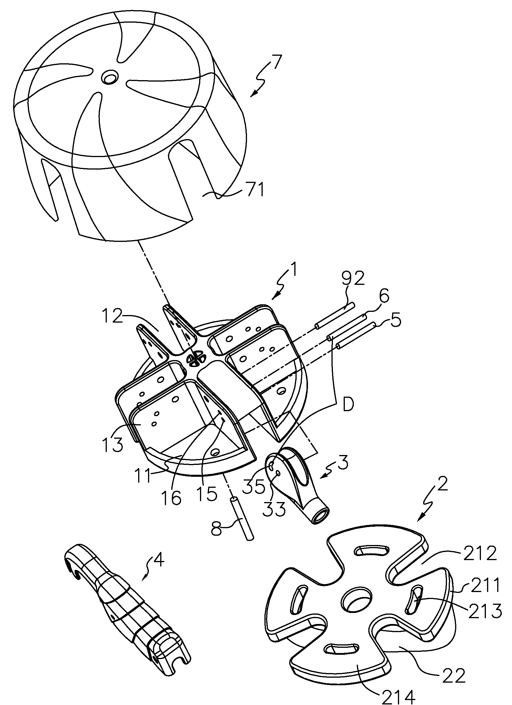
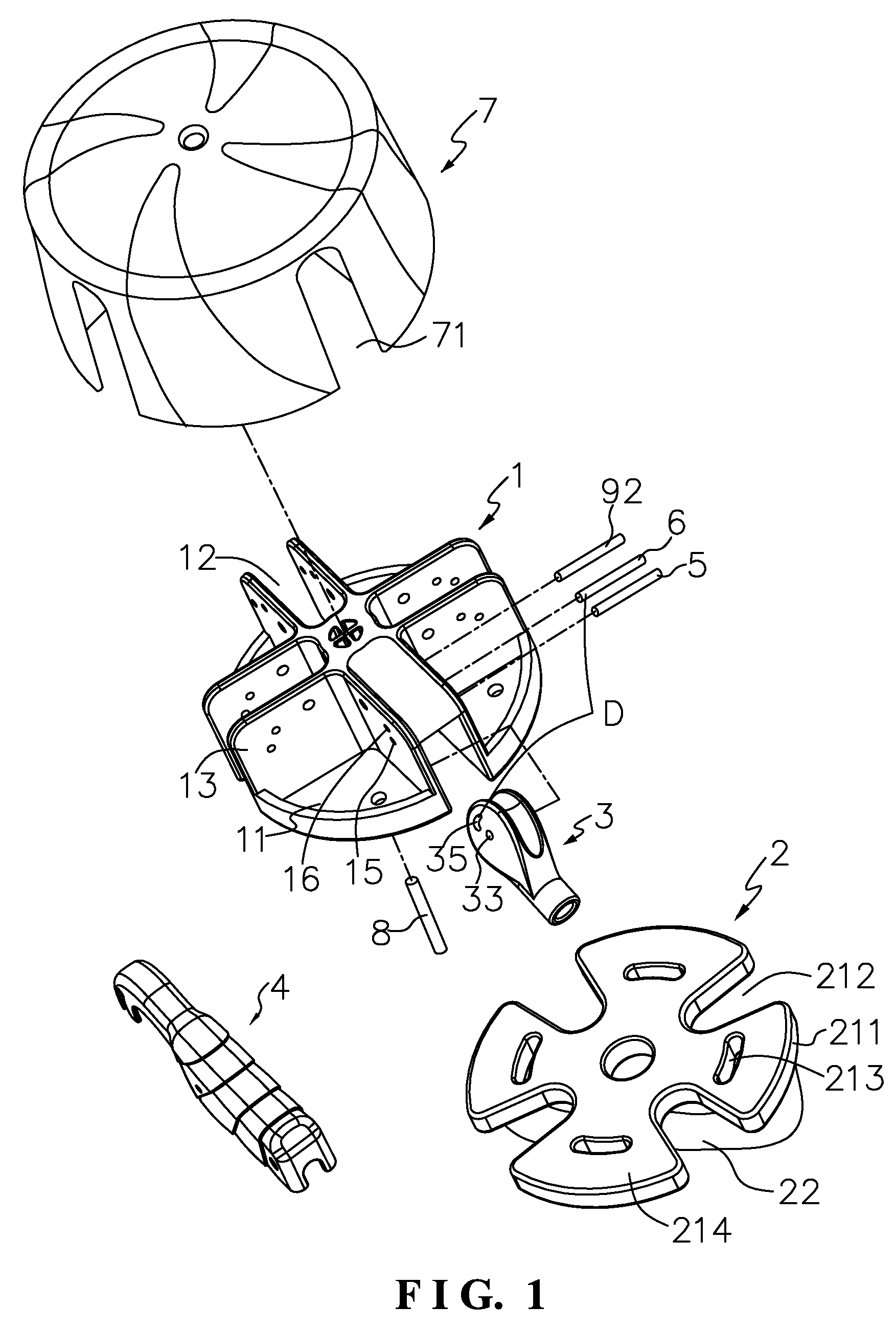
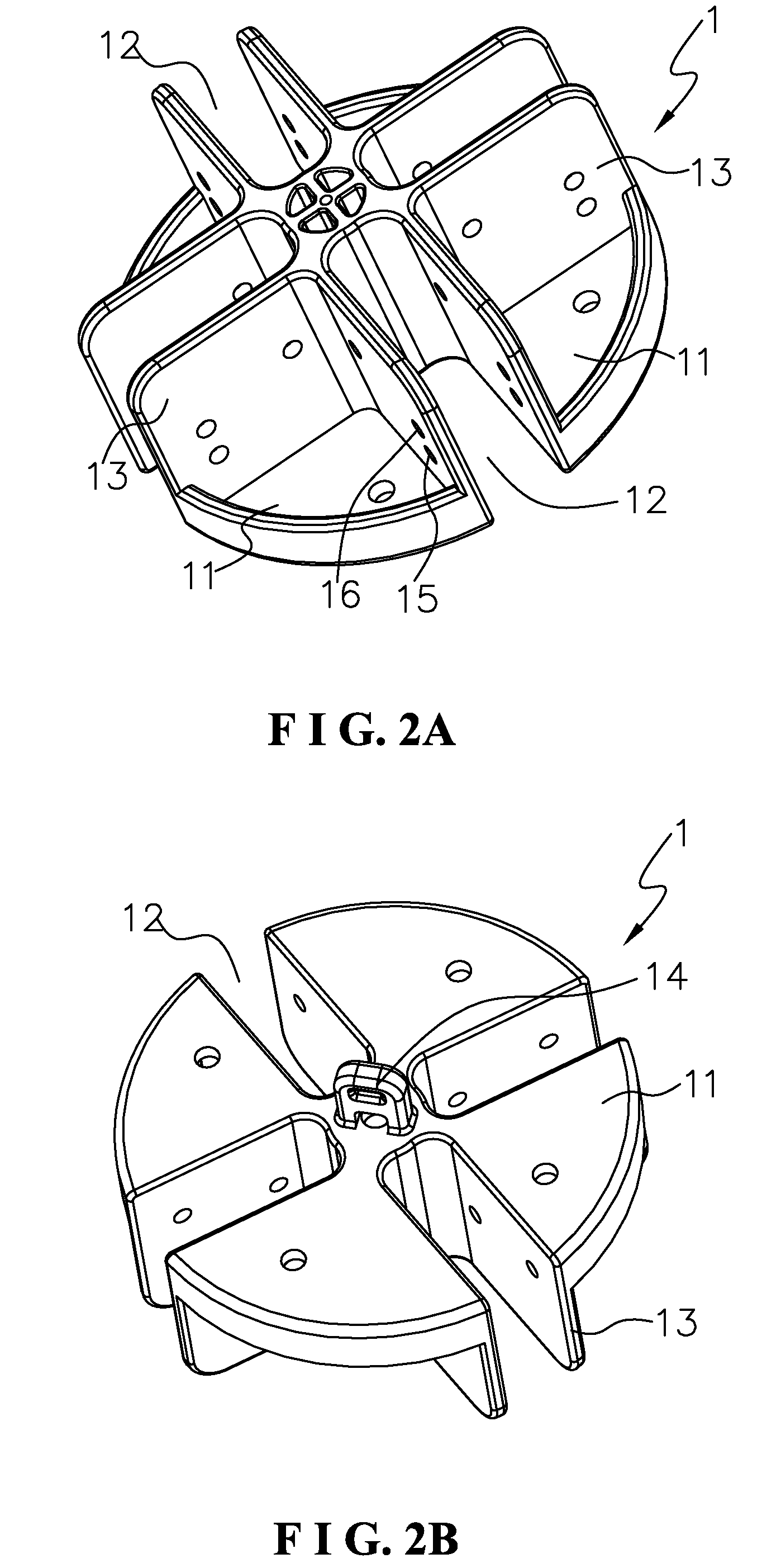
[0045]As shown in FIG. 1, FIG. 6 and FIG. 7, a top support structure of a tent frame according to a first embodiment of the present invention is connected with support poles 10 and elastic members 9. The elastic members 9 will be bent to store elastic energy when the tent is folded. The elastic members 9 can automatically spring the support poles 10 when the elastic energy is released.

[0046]The top structure comprises a pivot holder 1, a control holder 2, four connection heads 3, a decoration cover 4, a rotation shaft 5, a position-limit device D, and a top cover 7. The position-limit device D includes a positioning shaft 6 and a crescent groove 35 of the connection head 3.

[0047]The top cover 7 is coupled to the pivot holder 1. The control holder 2 is pivotally connected to the pivot holder 1 and rotatable with respect to the pivot holder 1. Inner ends of the four connection heads 3 are inserted through the notches 71 of the top cover 7 and pivotally connected to the pivot holder 1,...


PUM


Abstract

A top support structure of a tent frame includes a top pivot holder (1), to which a plurality of support poles (10) are pivotally coupled. An elastic member (9) is provided between each support pole and the pivot holder. The elastic member folds and stores elasticity energy when the tent frame is folded and automatically springs the support poles when the elasticity energy is released. A control holder (2) is pivotally coupled to the bottom of the pivot holder, and the control holder has lock pieces (211) which can prop the support poles up to limit their rotation and release grooves (212) adjacent to the lock pieces which can release the limitation. On the top of pivot grooves (12) of the pivot holder are provided with position-limited devices (D) to prevent the support poles from rotating upwards.

Description

BACKGROUND OF THE INVENTION[0001]1. Field of the Invention[0002]The present invention relates to a tent part, and more particularly to a top support structure of a tent frame.[0003]2. Description of the Prior Art[0004]A conventional automatic extendable tent frame comprises a top pivot holder. The pivot holder has pivot troughs for connection of support poles and elastic units which correspond in number to the support poles. When the support poles are folded downward with respect to the pivot holder, the elastic units provide elasticity. Each support pole is movably connected to the pivot holder and rotatable with relative to the pivot holder. One end of each elastic unit is connected to the support pole and another end of each elastic unit is connected to the pivot holder. It is required to apply a force to retract the support poles inward when folding the tent. When unfolding the tent, the restoring force of the elastic units will expand the support poles up relative to the pivot ...

Claims


Application Information

Patent Timeline
Patent Type & Authority Patents(United States)
IPC IPC(8): E04H15/48
CPCE04H15/48
Inventor LEE, SUNGHEE
Owner LEE SUNGHEE
Why Eureka
Try Eureka