Steel cord conveyer belt with a connecting hinge for coupling two belt ends

a conveyer belt and hinge technology, applied in the direction of belts, belt/chains/gearrings, belt fastenings, etc., can solve the problems of significant reduction of permissible tensile load, risk of steel wire breaking, and inability to accept hinge-like connections, etc., to achieve the effect of producing with little complexity

Active Publication Date: 2013-02-05
CONTITECH TRANSPORTBANDSYSTEME GMBH
View PDF16 Cites 11 Cited by
  • Summary
  • Abstract
  • Description
  • Claims
  • Application Information

AI Technical Summary

Benefits of technology

[0010]It is an object of the invention to provide a hinge connection even for steel cord conveyer belts or steel cord conveyer belt segments having average and larger cord diameters. The hinge connection is tension-proof and can be produced with little complexity.

Problems solved by technology

In the case of steel cord conveyer belts, the hinge-like connections have not been able to gain acceptance, since the tension-proof connection of the hinge parts to the belt ends constitutes an unresolved problem.
This leads to a significant reduction in the permissible tensile loading and to a risk of the steel wires breaking.
This construction is unsuitable for steel cord conveyer belts which transmit large forces and have relatively rigid steel cords.
In addition, the thickness of the entire belt cross section is inevitably increased in the region of the belt end by the construction, which is disadvantageous when the entire conveyer belt circulates in the conveyer system.

Method used


Image

  • Steel cord conveyer belt with a connecting hinge for coupling two belt ends
  • Steel cord conveyer belt with a connecting hinge for coupling two belt ends
  • Steel cord conveyer belt with a connecting hinge for coupling two belt ends

Examples


Embodiment Construction

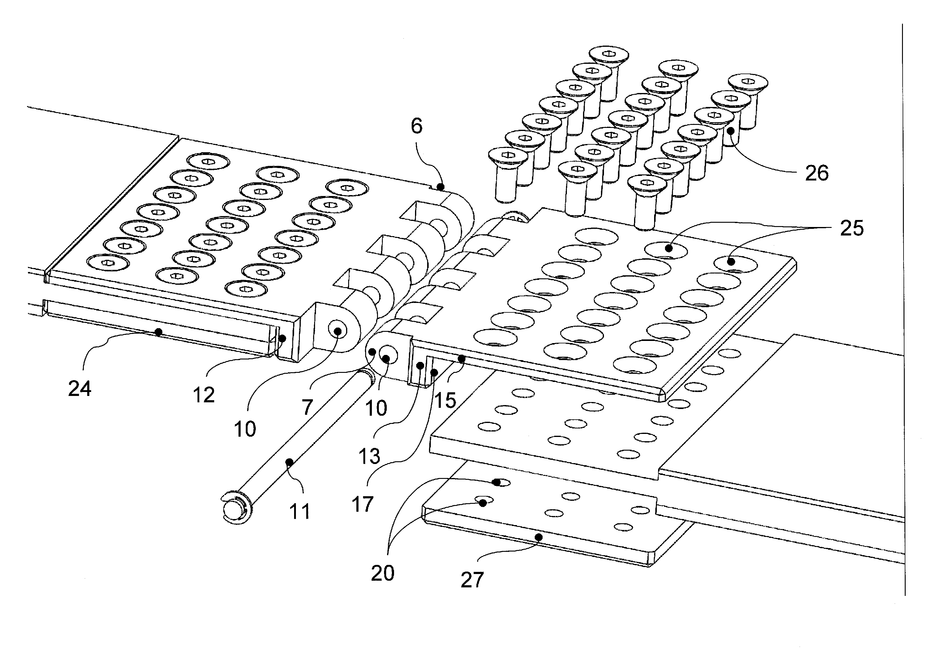
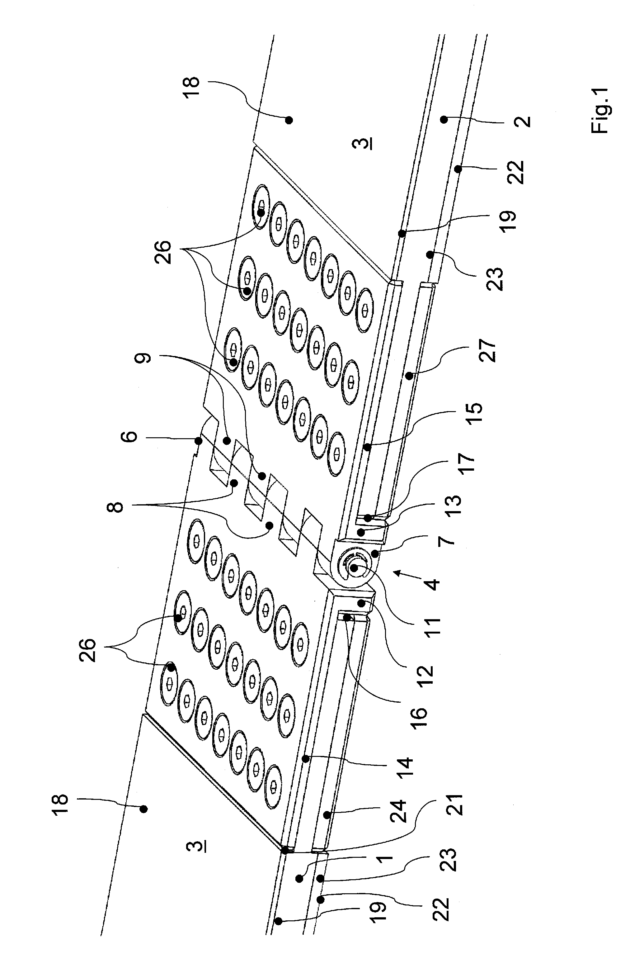
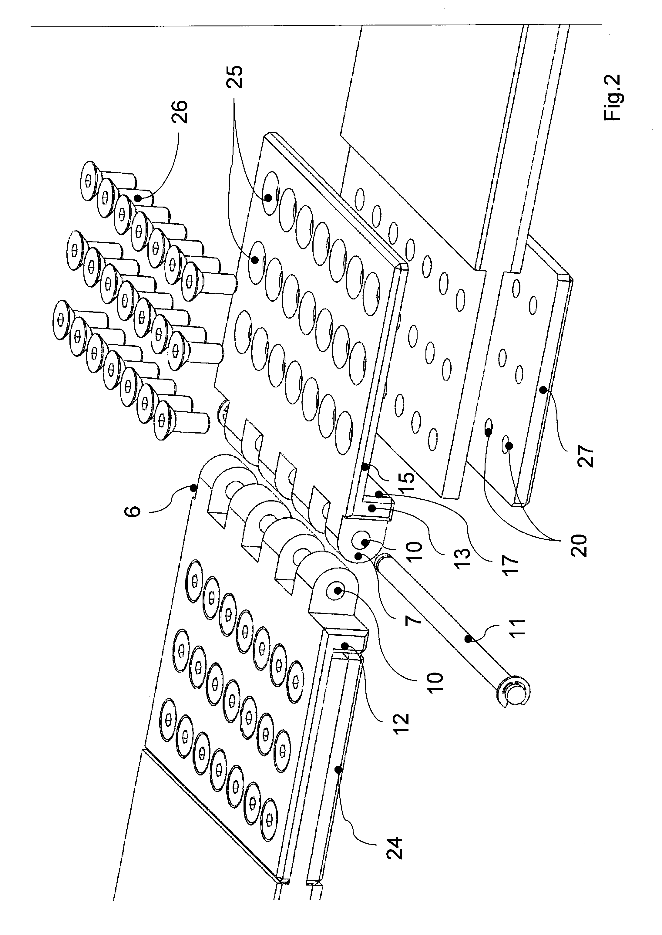
[0029]Two ends 1 and 2 of a steel cord conveyer belt 3 are connected to each other in a tension-resistant manner via a hinge 4 (FIG. 1). The steel cord conveyer belt 3 is constructed in a manner known per se from elastomeric material and has an embedded reinforcing support layer of steel cables or steel cords 5 arranged in parallel. To illustrate this embedding, the belt ends (1, 2) are illustrated in a transparent section in FIG. 3.

[0030]The hinge 4 is comprised of two part hinges 6 and 7 having crenellated projections 8 and 9 which intermesh in such a manner that the transverse bores 10 disposed in the projections 8 and 9 are aligned with each other to permit a coupling rod 11 to be introduced through the transverse bores 10 in order to complete the hinge 4. Each part hinge 6 or 7 comprises a hinge bar 12 or 13 carrying the crenellated projections (8, 9). The hinge bars (12, 13) have, facing away from the hinge, respective integrated clamping plates 14 and 15 which are integrally ...


PUM


Abstract

A conveyor belt with a reinforcement support layer consisting of steel cords running in parallel has, at each end, the hinge-like configuration for coupling to another belt end. In order also to provide a hinge connection for steel cord conveyor belts having relatively large cord diameters, each belt end (1, 2) has a part hinge (6, 7). Each part hinge (6 and 7) has a hinge bar (12 and 13) on which an integrated clamping plate (14 and 15) is integrally formed. The integrated clamping plate (14 and 15) is seated in the one belt outer surface (18) of the conveyor belt. On the opposite belt outer surface (22), a corresponding, separate clamping plate (24 and 27) is seated in each case in the rubber cover layer there. The clamping plate of each part hinge securely clamps the corresponding thickness-reduced belt end therebetween.

Description

CROSS REFERENCE TO RELATED APPLICATIONS[0001]This application is a continuation application of international patent application PCT / EP 2010 / 063945, filed Sep. 22, 2010, designating the United States and claiming priority from German application 10 2009 044 080.1, filed Sep. 23, 2009, and the entire content of both applications is incorporated herein by reference.FIELD OF THE INVENTION[0002]The invention relates to a conveyer belt or conveyer belt segment of elastomeric material with a reinforcing support layer of steel cords which run in the longitudinal direction of the conveyer belt and are arranged parallel to one another. Each belt or segment end has a formation for the hinge-like coupling together to another belt or segment end.BACKGROUND OF THE INVENTION[0003]It is known to join conveyer belts of elastomeric material continuously by the two ends of the conveyer belt being joined in the end regions after specific finishing of the rubber covering layers and by the ends being con...

Claims


Application Information

Patent Timeline
Patent Type & Authority Patents(United States)
IPC IPC(8): F16G3/02B65G15/30
CPCF16G3/09
Inventor MOESCHEN-SIEKMANN, MICHAELHUELS, ACHIM
Owner CONTITECH TRANSPORTBANDSYSTEME GMBH
Why Eureka
Try Eureka