
Deposit amount estimation device of engine

a technology of amount estimation and engine, which is applied in the direction of machines/engines, electrical control, instruments, etc., can solve the problems of engine output property and engine exhaust gas property decreasing, and achieve the effect of high frequency

Active Publication Date: 2014-10-28
TOYOTA JIDOSHA KK
View PDF12 Cites 4 Cited by
  • Summary
  • Abstract
  • Description
  • Claims
  • Application Information

AI Technical Summary

Benefits of technology

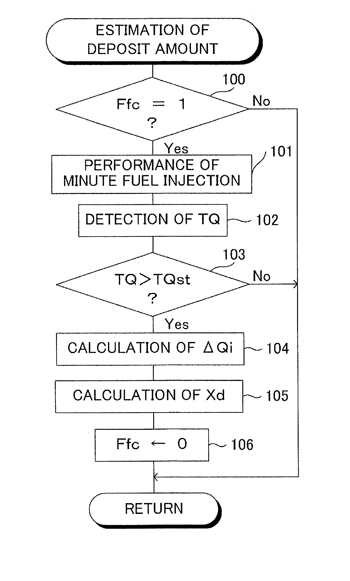
The patent text describes a method for estimating the amount of deposit in an engine by measuring the difference between the actual and base torque. This is done by performing a minute fuel injection during the fuel cut, which results in a small amount of torque. By measuring the torque produced by the minute injection, the amount of deposit can be accurately estimated. This method allows for frequent and accurate deposit estimation without affecting the engine's performance.

Problems solved by technology

Further, when the fuel of the desired amount is not injected from the fuel injector, the output property and the exhaust gas property of the engine may decrease.

Method used


Image

  • Deposit amount estimation device of engine
  • Deposit amount estimation device of engine
  • Deposit amount estimation device of engine

Examples


first embodiment

[0034]FIG. 4 is a view showing an example of a routine for performing an estimation of a deposit amount of the

second embodiment

[0035]FIG. 5 is a view showing an example of a routine for performing a minute fuel injection amount learning of the

[0036]FIG. 6 is a view showing an example of a routine for performing the estimation of the deposit amount of the second embodiment.

third embodiment

[0037]FIG. 7 is a view showing an example of a routine for performing the estimation of the deposit amount of the


PUM


Abstract

The invention relates to a deposit amount estimation device for estimating a deposit amount by calculating an amount of a deposit on an injection hole wall face of a fuel injector (22). An increment judgment of whether an actual fuel injection amount is larger than the required fuel injection amount corresponding thereto when a fuel injection command value corresponding to a required fuel injection amount smaller than a predetermined amount is given to the fuel injector, is performed, and when it is judged that the actual fuel injection amount is larger than the required fuel injection amount corresponding thereto by the increment judgment, the deposit amount is estimated on the basis of the difference between the actual fuel injection amount and the required fuel injection amount corresponding thereto.

Description

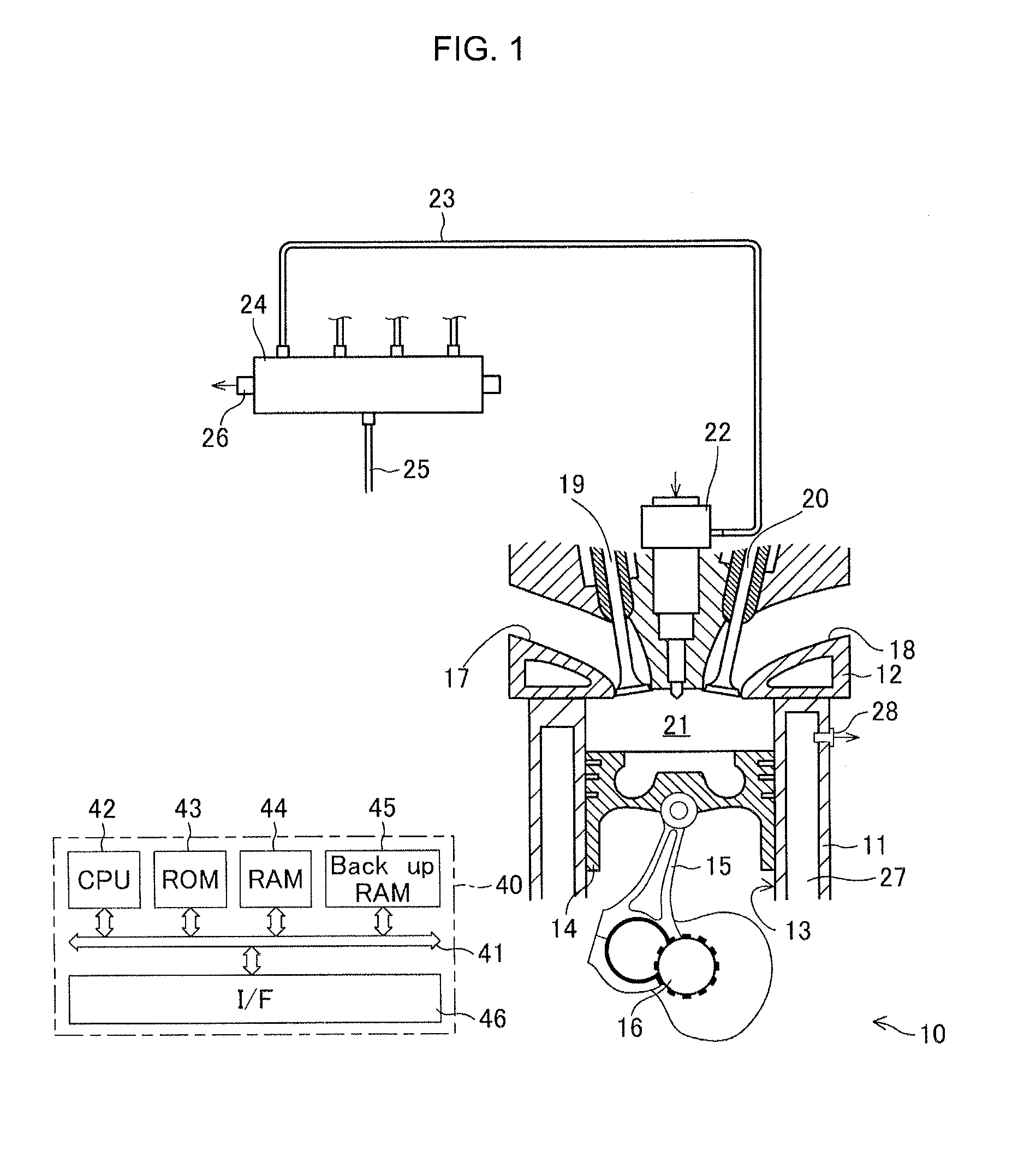
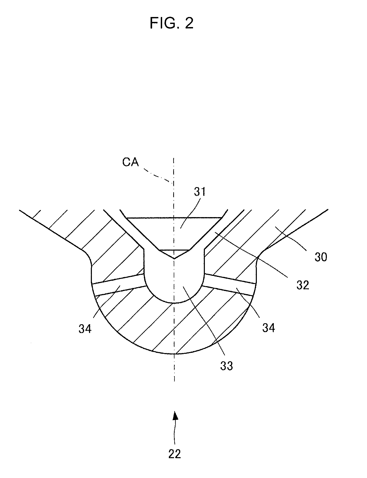
CROSS REFERENCE TO RELATED APPLICATIONS[0001]This application is a National Stage of International Application No. PCT / JP2011 / 060026 filed Apr. 25, 2011, the contents of all of which are incorporated herein by reference in their entirety.TECHNICAL FIELD[0002]The invention relates to a deposit amount estimation device of an engine.BACKGROUND ART[0003]An engine comprising fuel injectors arranged such that a fuel is injected directly into combustion chambers, is known. In such an engine, it is also known that a combustion product (i.e. a substance derived from the combustion of the fuel) deposits on an injection hole outlet adjacent wall face of the fuel injector (i.e. a fuel injector wall face adjacent to the outlet of the fuel injection hole of the fuel injector). In the case that combustion products deposit on the injection hole outlet adjacent wall face, even when a command is given to the fuel injector for making the injector inject a desired amount of fuel, the fuel of the desire...

Claims


Application Information

Patent Timeline
Patent Type & Authority Patents(United States)
IPC IPC(8): F02D41/22G01M15/04F02M65/00
CPCF02D41/221F01N2900/1602Y02T10/40F02M65/00F02D2200/0614
Inventor IKEMOTO, MASATO
Owner TOYOTA JIDOSHA KK
Learn More