Apparatus using light-attenuating element for optically reproducing and recording information

a technology of light-attenuating elements and optical reproduction, which is applied in the field of apparatuses for optically reproducing information, can solve the problems of unstable reproducing and recording, difficult to achieve sufficient signal-to-noise ratios of regenerative signals, and noisy blue lasers, and achieve stable reading-writing operations and simplified structure

Inactive Publication Date: 2006-12-14
CANON KK
View PDF8 Cites 3 Cited by
  • Summary
  • Abstract
  • Description
  • Claims
  • Application Information

AI Technical Summary

Benefits of technology

[0025] The present invention can provide an apparatus for optically reproducing and recording information having a simplified structure and realizing stable reading-writing operations.

Problems solved by technology

Blue lasers are noisy at low powers of 3 mW or lower, and sufficient signal-to-noise (S / N) ratios of regenerative signals are difficult to achieve.
When lasers having a large aspect ratio of the major axis of the ellipse to the minor axis are used, required resolution cannot be achieved either in a direction parallel to tracks or in a direction perpendicular to the tracks, resulting in unstable reproducing and recording.
However, an apparatus including both the light-attenuating element and the beam-shaping element becomes large and results in an increase in cost.

Method used


Image

  • Apparatus using light-attenuating element for optically reproducing and recording information
  • Apparatus using light-attenuating element for optically reproducing and recording information
  • Apparatus using light-attenuating element for optically reproducing and recording information

Examples


first embodiment

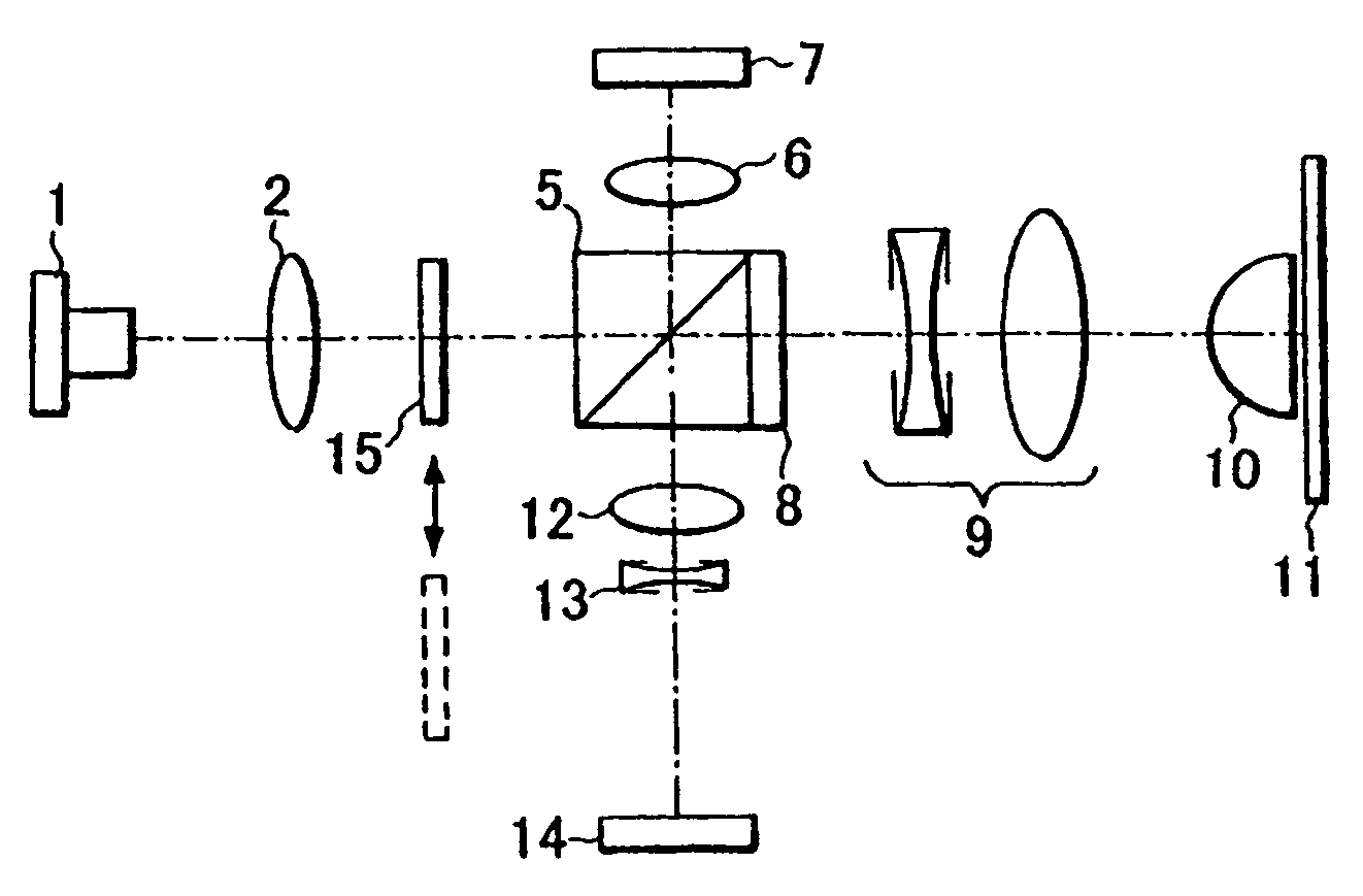
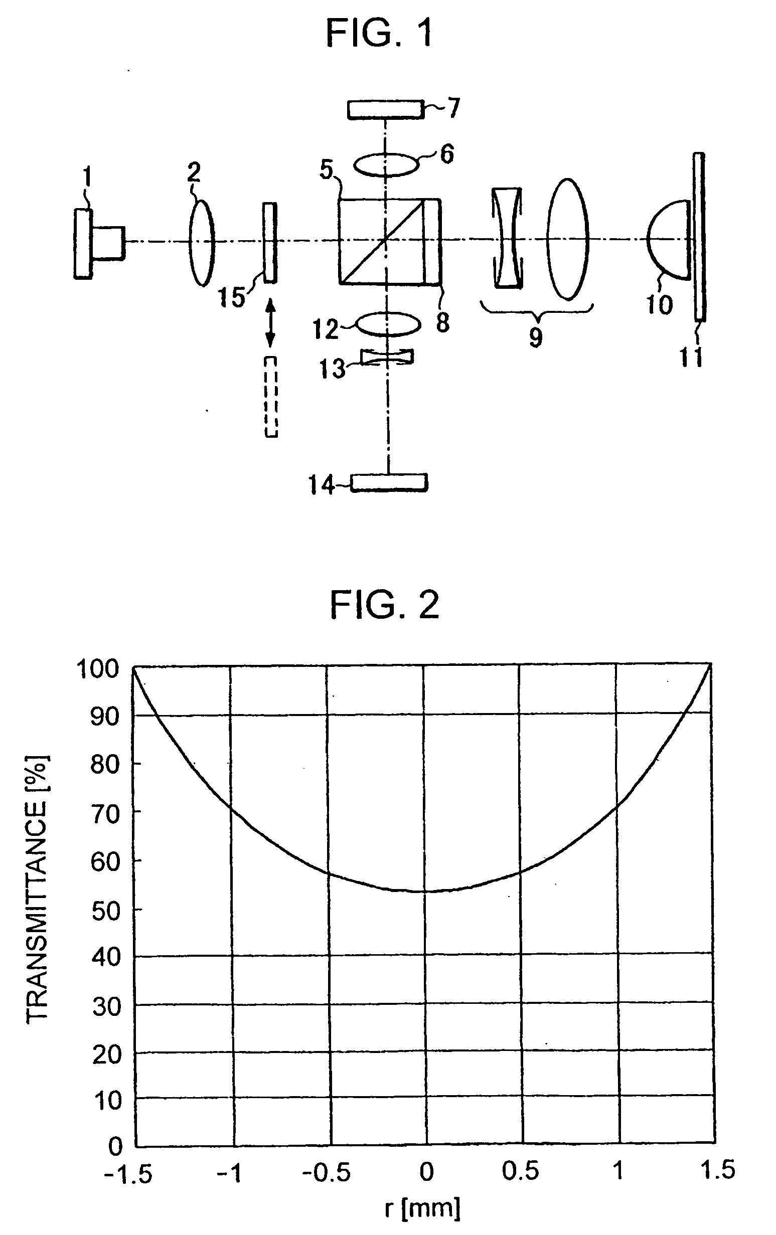
[0048]FIG. 1 illustrates an overview of an apparatus for optically reproducing and recording information according to a first embodiment of the present invention.

[0049] Divergent elliptical light beams emitted from a semiconductor laser 1 are collimated by a collimating lens 2, and enter a polarized-beam splitter 5.

[0050] Part of the incident beams is reflected, and is converged on a front-monitoring photodiode 7 by a monitoring lens 6.

[0051] The output of the semiconductor laser 1 is controlled on the basis of the output of this front-monitoring photodiode 7.

[0052] On the other hand, the light beams passing through the polarized-beam splitter 5 are converted into circularly polarized light beams by a quarter-wave plate 8, and the resultant beams enter a beam expander 9.

[0053] The beam expander 9 includes a combination of a concave lens and a convex lens. The concave lens is movable in the optical-axis direction so as to correct spherical aberration generated by an error in thi...

second embodiment

[0074]FIG. 5 illustrates an overview of an apparatus for optically reproducing and recording information according to a second embodiment of the present invention. Like reference numerals will be used to indicate elements similar to those in the first embodiment.

[0075] Divergent elliptical light beams emitted from a semiconductor laser 1 are collimated by a collimating lens 2, and enter a polarized-beam splitter 5.

[0076] Part of the incident beams is reflected, and is converged on a front-monitoring photodiode 7 by a monitoring lens 6.

[0077] The output of the semiconductor laser1 is controlled on the basis of the output of this front-monitoring photodiode 7.

[0078] On the other hand, the light beams passing through the polarized-beam splitter 5 are converted into circularly polarized light beams by a quarter-wave plate 8, and the resultant beams enter a beam expander 9.

[0079] The beam expander 9 includes a combination of a concave lens and a convex lens. The concave lens is mova...

third embodiment

[0104]FIG. 11 illustrates an overview of an apparatus for optically reproducing and recording information according to a third embodiment of the present invention. Like reference numerals will be used to indicate elements similar to those in the first and second embodiments.

[0105] Divergent elliptical light beams emitted from a semiconductor laser 1 are collimated by a collimating lens 2, and enter a polarized-beam splitter 5.

[0106] Part of the incident beams is reflected, and is converged on a front-monitoring photodiode 7 by a monitoring lens 6.

[0107] The output of the semiconductor laser 1 is controlled on the basis of the output of this front-monitoring photodiode 7.

[0108] On the other hand, the light beams passing through the polarized-beam splitter 5 are converted into circularly polarized light beams by a quarter-wave plate 8, and the resultant beams enter a beam expander 9.

[0109] The beam expander 9 includes a combination of a concave lens and a convex lens. The concave...


PUM

PropertyMeasurementUnit
wavelengthsaaaaaaaaaa
powersaaaaaaaaaa
aspect ratioaaaaaaaaaa

Abstract

An apparatus for optically recording information in a recording medium and for optically reproducing the recorded information includes a semiconductor laser, an objective lens that focuses light beams from the laser on the recording medium, and a light-attenuating element for attenuating an amount of light of the light beams. The light-attenuating element has a transmittance distribution for shaping the section of the light beams into an approximate circle.

Description

BACKGROUND OF THE INVENTION [0001] 1. Field of the Invention [0002] The present invention relates to apparatuses for optically reproducing information from and recording information onto recording media. [0003] 2. Description of the Related Art [0004] To date, optical pickups having semiconductor lasers as light sources have been used in apparatuses for optically reproducing and recording information from and onto recording media. [0005] Recently, wavelengths of the lasers have been decreasing as recording of information has been becoming more highly densified, and systems using blue-violet semiconductor lasers having a wavelength of 400 nm have been put to practical use. [0006] Blue lasers are noisy at low powers of 3 mW or lower, and sufficient signal-to-noise (S / N) ratios of regenerative signals are difficult to achieve. [0007] To solve this problem, methods for reducing laser noise by disposing neutral-density (ND) filters on optical paths during reproducing are proposed in Japa...

Claims


Application Information

Patent Timeline
Patent Type & Authority Applications(United States)
IPC IPC(8): G11B7/00
CPCG11B7/1381G11B2007/0013G11B7/1398
Inventor NAGURA, CHIHIRO
Owner CANON KK
Why Eureka
Try Eureka