Bracket assembly for a rack

a bracket and rack technology, applied in the field of bracket assemblies, can solve problems such as insufficient engagemen

Active Publication Date: 2013-02-12
KING SLIDE WORKS CO LTD
View PDF27 Cites 116 Cited by
  • Summary
  • Abstract
  • Description
  • Claims
  • Application Information

AI Technical Summary

Benefits of technology

[0004]The present invention relates to a bracket assembly, and the bracket assembly is reliable and strong enough to be mounted in a rack.
[0016]Preferably, the bracket assembly further comprises a support frame assembly which includes a first support frame and a second support frame, the first support frame including a first support portion for connecting with a first extension plate, the second support frame being adapted to support a load member for movably connecting with a second extension plate, the second support frame including a stop member, the second extension plate including a first block and a second block which is spaced away from the first block, the stop member being located between the first and second blocks and stopped by one of the first and second blocks for restricting the travel distance of the second extension plate relative to the second support frame.

Problems solved by technology

This can only provide a temporary positioning feature and the engagement is not strong enough especially when a heavy load is connected with the bracket.

Method used


Image

  • Bracket assembly for a rack
  • Bracket assembly for a rack
  • Bracket assembly for a rack

Examples


first embodiment

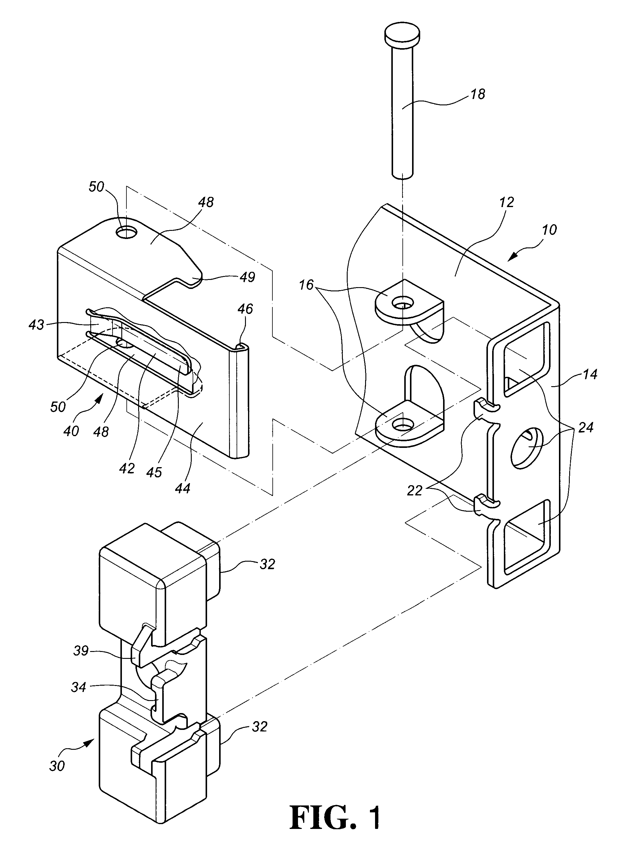
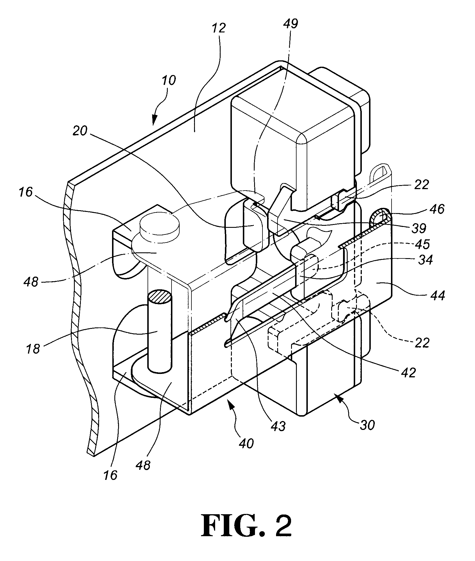
[0043]Referring to FIGS. 1 and 2, a bracket assembly according to the present invention comprises a bracket 10, a base 30, and a fastening member 40.

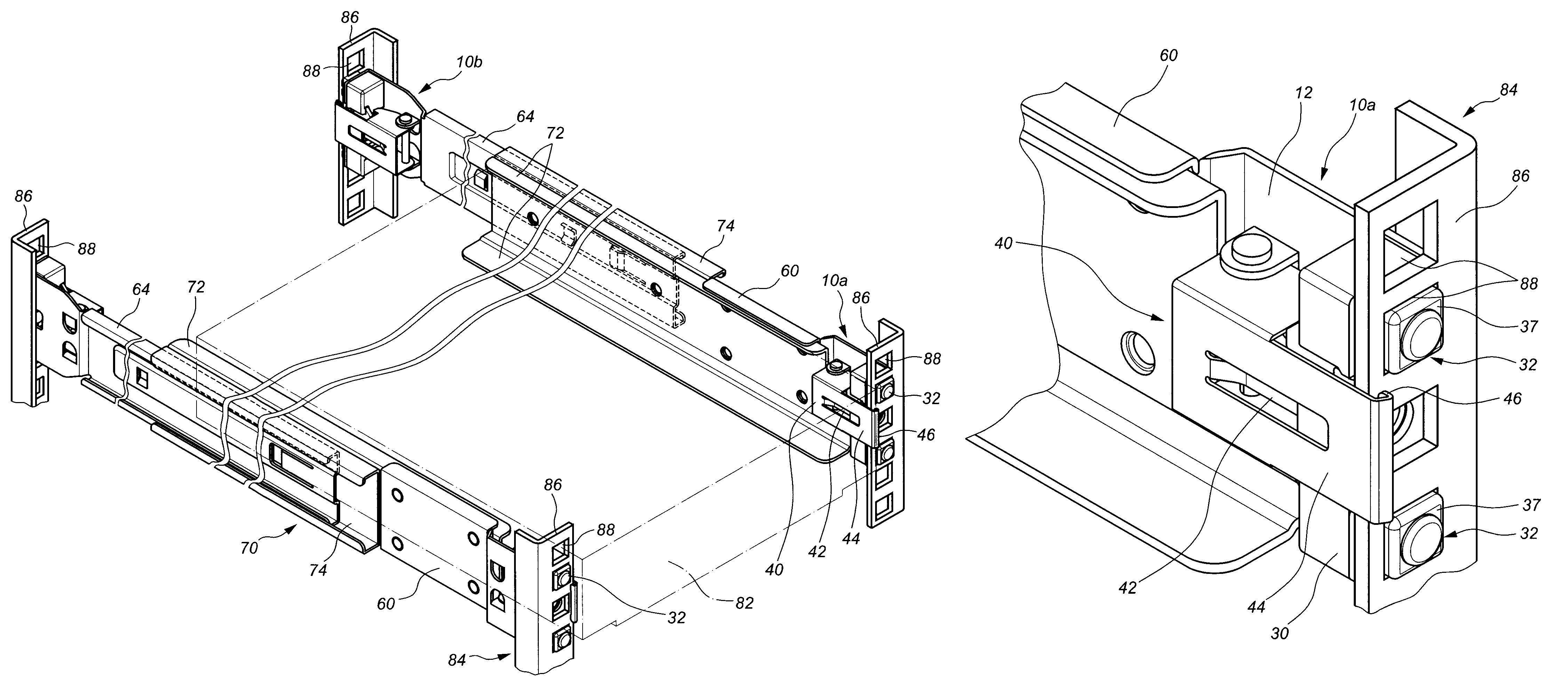
[0044]The bracket 10 includes a first plate 12 and a second plate 14 which is substantially extending vertically from an end of the first plate 12. The first plate 12 includes two lugs 16, a pin 18 penetrating through the two lugs 16, and a first engaging portion 20 extending from the first plate 12, as shown in FIG. 2. The second plate 14 includes two second engaging portions 22 and a plurality of bracket holes 24. In this embodiment, the bracket holes 24 include rectangular holes and circular holes. As shown in FIGS. 3 and 4, the bracket 10 includes a first bracket 10a and a second racket 10b which have the same configuration as the bracket 10.

[0045]The base 30 is securely connected to the bracket 10. The base 30 includes a plurality of connection members 32 corresponding to the bracket holes 24. In this embodiment, at least one of th...

third embodiment

[0053]Referring to FIGS. 14 and 15, a bracket assembly according to the present invention comprises a bracket 10, a plurality of connection members 32, and a fastening member 40.

[0054]The bracket 10 includes a first plate 12 and a second plate 14 which extends from an end of the first plate 12. The first plate 12 includes two lugs 16 and a pin 18 penetrating through the two lugs 16. The second plate 14 includes a plurality of bracket holes 24 thereon. At least one of the connection members 32 is located corresponding to at least one of the bracket holes 24. The fastening member 40 is pivotally connected to the first plate 12 of the bracket 10. The fastening member 40 includes a resilient leg 42 and a fastening arm 44 extending from the fastening member 40. The resilient leg 42 includes a fixing end 43 and a free end 45. The fixing end 43 of the resilient leg 42 is fixed to the fastening member 40 and the free end 45 of the resilient leg 42 leans on the bracket 10. In this embodiment...


PUM


Abstract

A bracket assembly for a rack is provided. The rack has a plurality of holes. The bracket assembly includes a bracket having multiple bracket holes, a base securely connected to the bracket, and a fastening member pivotally connected to the bracket. The base includes multiple connection members corresponding to the bracket holes. The fastening member includes a resilient leg and a fastening arm. The fastening arm has at least one fastening portion. One of the connection members is inserted into one of the holes of the rack. The fastening portion of the fastening arm is hooked to the rack so as to connect the bracket to the rack.

Description

FIELD OF THE INVENTION[0001]The present invention relates to a bracket assembly, and more particularly, to a bracket assembly for a rack.BACKGROUND OF THE INVENTION[0002]A conventional bracket assembly for a rack is disclosed in U.S. Pat. No. 7,357,362, titled “Bracket Positioning Structure for a Slide” to Yang, and US Published Number 2003 / 0107309, titled “Dual Flat Springs for Tool-Less Slide Installation” to Lauchner. Lauchner discloses the use of two springs. The end of one spring leans on a frame of a rack. Yang discloses an arm having at least a toothed portion which is urged by a spring so as to engage with the frame.[0003]The arm disclosed by Yang includes the toothed portion which is engaged with the frame, however, only the cross section of the toothed portion, a thickness of a board-like piece, is engaged with the frame. This can only provide a temporary positioning feature and the engagement is not strong enough especially when a heavy load is connected with the bracket....

Claims


Application Information

Patent Timeline
Patent Type & Authority Patents(United States)
IPC IPC(8): A47F7/00
CPCA47B88/044A47B96/06H05K7/1421A47B88/43H05K7/1489A47B88/423A47B57/545
Inventor CHEN, KEN CHINGYANG, SHUN HOHUANG, CHIEN LIWANG, CHUN CHIANG
Owner KING SLIDE WORKS CO LTD
Why Eureka
Try Eureka