Child seat mountable vehicle seat

a vehicle seat and seat technology, applied in the field of child seat mountable vehicle seats, can solve the problem of seat skin biting by the latching device, and achieve the effects of preventing the skin biting of the seat, and facilitating the latching movement of the latching devi

Inactive Publication Date: 2013-02-12
TS TECH CO LTD
View PDF2 Cites 2 Cited by
  • Summary
  • Abstract
  • Description
  • Claims
  • Application Information

AI Technical Summary

Benefits of technology

[0008]One object of the invention is to provide a configuration for preventing the biting of a seat skin by a latching device at an edge of the seat skin defining an opening when moving the latching device to latch a striker in a configuration where a fasting shaft of the strider device projects to a sitting surface of a seat cushion from the opening provided in the seat skin.
[0013]According to the first aspect of the invention, in the seat skin of the child seat mountable vehicle seat, the opening is defined by the non-stitched portion so that the belt-like portion of the front skin is turned over from the non-stitched portion towards the inner surface side of the front skin so as to extend forwards, the belt-like portion of the rear skin is caused to extend forwards further than the vertical shaft portions of the metal striker, and the belt-like portion of the front skin is superposed on the belt-like portion of the rear skin with respect to the direction in which the latching device is moved to latch the metal striker. As a result, the edges of the front and rear seat skins which define the non-stitched portion do not enter the opening of the latching device as the latching device moved to latch the metal striker, thereby surely preventing the biting of the seat skin by the latching device.
[0014]Further, the beautifully-fringed non-stitched portion can be provided so as to withstand frequent latching movements of the latching device on the metal striker without deformation, by applying the trim plate along the inner surface side of the rear skin, stitching the tongue portion to the belt-like portion of the rear skin which extends forwards further than the vertical shaft portions of the metal striker and stitching the strip portions to both the ends of the non-stitched portion.
[0015]According to the second aspect of the invention, by forming the recessed cutout portion having the width corresponding to the width of the latching device in the trim plate at the center of the connecting portion so as to extend forwards from the rear edge of the connecting portion, the resistance to the latching movement of the latching device by the trim plate is suppressed to a lower level, and therefore, the latching movement of the latching device can be facilitated.
[0016]According to the third aspect of the invention, by further forming the slit cutout portion in the trim plate at the center of the tongue portion so as to extend forwards from the inner edge of the recessed cutout portion, the tongue portion of the trim plate which extends forwards further than the vertical shaft portions of the metal striker deflects in association with the latching movement of the latching device, and therefore, the latching movement of the latching device can be facilitated.
[0017]According to the fourth aspect of the invention, the trim cord is stitched transversely to the belt-like portion of the front skin of the seat skin which is turned over towards the inner surface side of the front skin. Therefore, the trim cord is held by a cushion pad, and even when the latching device is moved to latch the metal striker frequently, the belt-like portion of the front skin can be prevented from being turned back to be forced out of the opening defined by the non-stitched portion.

Problems solved by technology

When the latching devices are moved to latch the inverted-U-shaped shafts of the strikers, an edge of the seat skin defining the opening may enter an opening of the latching device to cause the biting of the seat skin by the latching device.

Method used


Image

  • Child seat mountable vehicle seat
  • Child seat mountable vehicle seat
  • Child seat mountable vehicle seat

Examples


Embodiment Construction

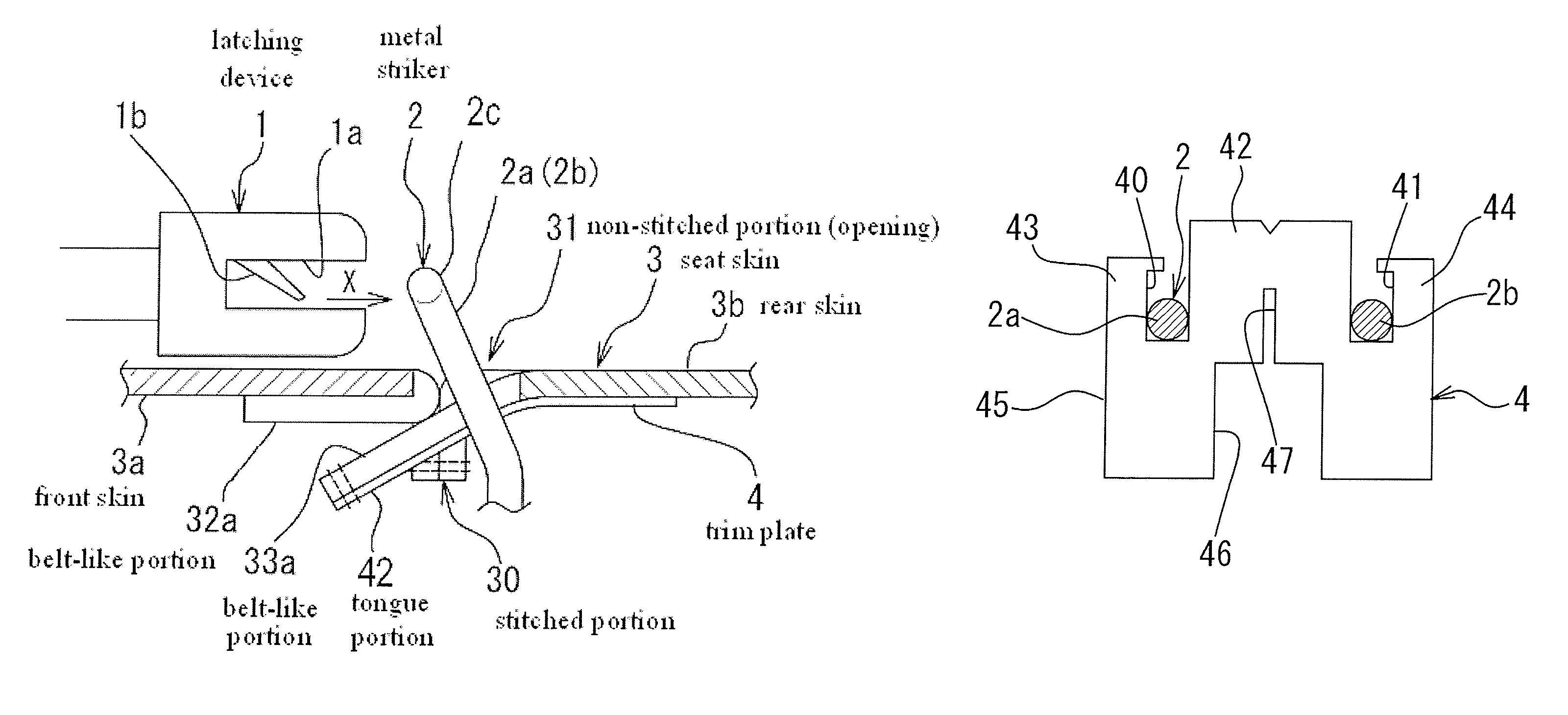
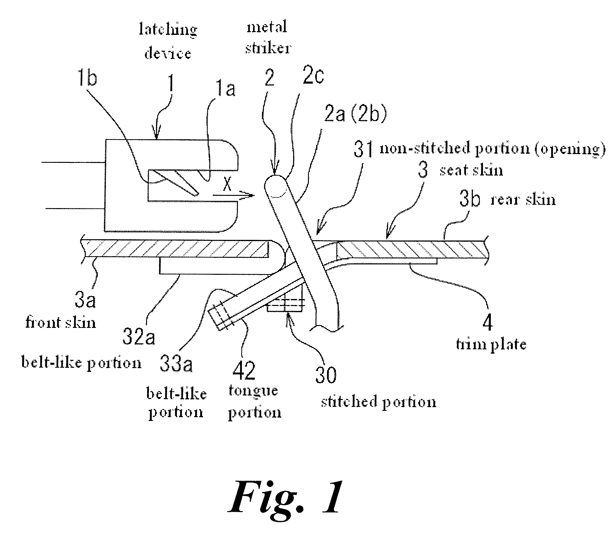
[0027]An embodiment exemplifies a rear seat on which a child seat (not shown) is mounted. The rear seat has a seat cushion (not shown) having a seat skin 3 formed of a front skin 3a and a rear skin 3b. Ends of the front skin 3a and the rear skin 3b are stitched together to form a stitched portion 30. And, a non-stitched portion 31 is provided in apart of the stitched portion 30. A metal striker 2 on which a latching device 1 of the child seat is to be latched is caused to project to a sitting surface side of the seat cushion through the non-stitched portion 31. Hereinafter, words such as “front” and “rear” denote directions towards the front and rear of a vehicle body, respectively.

[0028]An arm extends from a rear portion of the child seat, and the latching device 1 is attached to a rear end portion of the arm. This latching device 1 has a holding opening 1a to receive the metal striker 2 and a latch 1b to detachably engage with the metal striker 2. A pair of the latching devices 1 ...


PUM


Abstract

A child seat mountable vehicle seat, includes: a seat skin including a front skin and a rear skin; a stitched portion; and a non-stitched portion formed in the stitched portion to define an opening from which a metal striker is projected. An extension portion of the front skin is turned over and extends forwards, while an extension portion of the rear skin extends forwards further than the metal striker. A trim plate is applied along an inner surface side of the rear skin, and in the non-stitched portion, the extension portion of the front skin is superposed on the extension portion of the rear skin with respect to a direction in which a latching device is moved to latch the metal striker.

Description

CROSS-REFERENCE TO RELATED APPLICATION(S)[0001]This application claims priority from Japanese Patent Application No. 2009-297670 filed on Dec. 28, 2009, the entire contents of which are incorporated herein by reference.BACKGROUND[0002]1. Field of the Invention[0003]The present invention relates to a child seat mountable vehicle seat in which a child seat is fixedly mounted on a sitting surface of a seat cushion by latching and locking latching devices of the child seat on metal staple-shaped strikers which project from the sitting surface of the seat cushion in positions lying closer to a rear portion of the seat cushion.[0004]2. Description of the Related Art[0005]There is discloses a vehicle seat in which a child seat is mountable (JP-2002-301963-A). In the vehicle seat, metal strikers are provided on a seat cushion frame in a rising posture, at a rear portion of a seat cushion. And, latching devices provided on the child seat are latched thereon (JP-2002-301963-A).[0006]Each of t...

Claims


Application Information

Patent Timeline
Patent Type & Authority Patents(United States)
IPC IPC(8): B60N2/28B60N2/90
CPCB60N2/2881B60N2/58B60N2/2887
Inventor ABE, KATSUHIKOMATSUZAKI, TSUTOMU
Owner TS TECH CO LTD
Why Eureka
Try Eureka