Disc brake pad assembly

a technology of disc brake pads and assembly parts, which is applied in the direction of braking components, noise/vibration control, braking elements, etc., can solve the problems of uneven orientation of both pads, easy to observe the degree of partial wear of the lining, and unstable orientation of both pads. to achieve the effect of suppressing the projection of a pad

Active Publication Date: 2014-12-11
AKEBONO BRAKE IND CO LTD
View PDF3 Cites 13 Cited by
  • Summary
  • Abstract
  • Description
  • Claims
  • Application Information

AI Technical Summary

Benefits of technology

[0023]According to the disc brake pad assembly configured as described under (1) above, the construction can be realized in which both the inner and outer shim plates are assembled together in such a manner as not only to be displaced circumferentially relative to each other but also not to be separated inadvertently and moreover in which the projection of the pad from both the inward and outward circumferential edges of the pressure plate is suppressed to a low level. Namely, in the case of the disc brake pad assembly configured as described under (1) above, the separation of the inner and outer shim plates is prevented by the engagement between the locking through holes and the locking projecting pieces which are provided in and at the circumferential end portions of both the shim plates. Consequently, although the inner locking pieces provided on the inner shim plate are fittingly superposed on the outer locking pieces provided on the outer shim plate in the conventional construction shown in FIGS. 13 to 15, the inner locking pieces and the outer locking pieces do not have to be fittingly superposed on each other. As in the disc brake pad assembly configured as described under (3) above, even when the inner and outer locking pieces which are formed on both the inner and outer shim plates are locked on both the inward and outward circumferential edges of the pressure plate so as to retain both the shim plates on the pressure plate, the locking pieces are in engagement with the corresponding portions on the inward and outward circumferential edges without being superposed one on the other, whereby the projection of the locking pieces can be suppressed to a low level. Additionally, the assembling work of assembling both the shim plates together can be facilitated by adopting the configuration described under (2) above.
[0024]In addition to the function and advantage which are obtained by the disc brake pad assembly configured as described under (3) above, a construction can be realized at low costs by adopting the configuration described under (4) above in which a smooth circumferential displacement of the outer locking pieces relative to the circumferential edge portions of the pressure plate can be executed.
[0025]Namely, since the circumferential edge portions and the one surface of each of the outer locking pieces are spaced apart from each other at the portions which lie close to the circumferential ends of the one surface based on the presence of the projecting portions formed on the circumferential edge portions of the pressure plate, the end edges of the one surface which have the sharp shape (the radius of curvature of its cross section is almost 0) are never brought into frictional contact with the circumferential edge portions of the pressure plate. Because of this, the circumferential end edges of the outer locking pieces are prevented from biting into the circumferential edge portions, which enables a smooth circumferential displacement of the shim plate relative to the pressure plate.

Problems solved by technology

Then, a moment is exerted on both the pads in a direction in which a leading side of the rotor approaches (falls towards) both the pads based on the offset equaling the thickness of the linings, and this easily makes the orientations of both the pads unstable.
In case the orientations of both the pads become unstable when the brakes are applied, it becomes difficult that both the pads behave smoothly, and these pads are caused to vibrate, whereby noise referred to as a “brake squeal” is easily generated or the degree of partial wear of the linings easily becomes remarkable.
Although the installation space of the disc brake is limited, the constituent members including the caliper and the like are required to have a large magnitude of rigidity.
Because of this, the fact that the prevention of the interference needs to be taken into consideration becomes disadvantageous from the viewpoint of ensuring the degree of freedom in designing the disc brake.

Method used


Image

  • Disc brake pad assembly
  • Disc brake pad assembly
  • Disc brake pad assembly

Examples


Embodiment Construction

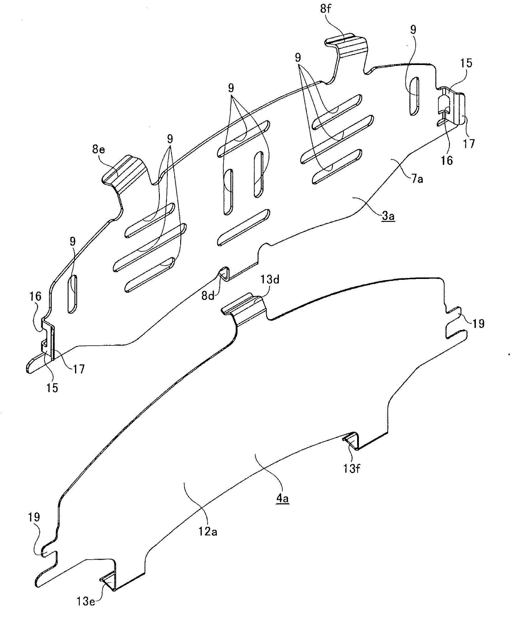
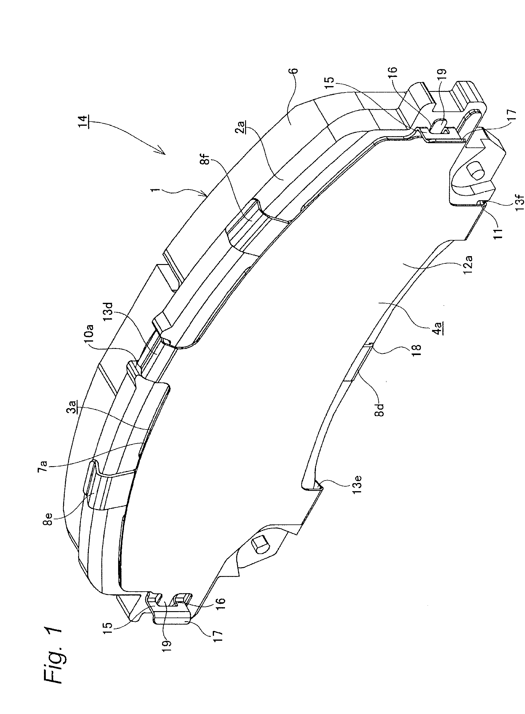
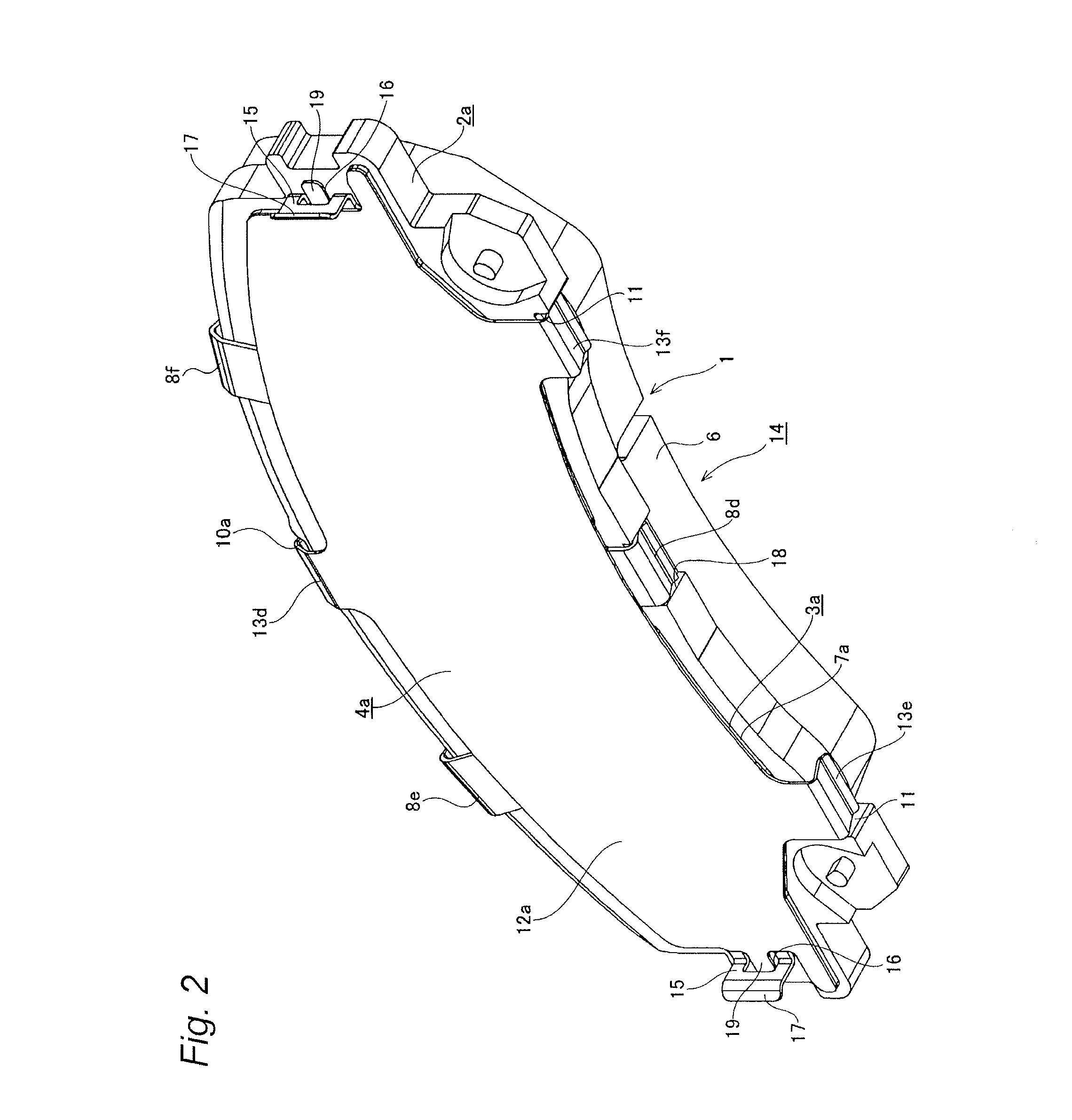
[0042]FIGS. 1 to 12 show an embodiment of a disc brake pad assembly according to the invention which corresponds to the configurations described under (1) to (5) above. A disc brake pad assembly 14 according to the embodiment includes a pad 1, an inner shim plate 3a, and an outer shim plate 4a.

[0043]The pad 1 has a lining 6 which is additionally fixed to a front surface of a pressure plate 2 and is disposed at a portion which faces an axial side surface of a rotor, not shown. A locking recess portion 10a is formed in a circumferential central portion of a radially outward circumferential edge portion of the pressure plate 2a, and a pair of step portions 11, 11 are formed at portions which lie close to both circumferential ends of a radially inward edge portion.

[0044]Additionally, the inner shim plate 3a is fabricated by press stamping and bending a corrosion-resistant and elastic metallic plate including a stainless spring steel plate, a stainless spring steel plate in which rubber...


PUM


Abstract

A disc brake pad assembly includes a pair of locking bent portions formed at circumferential end portions of an inner shim plate by being bent towards an opposite side to a pressure plate. Locking through holes are formed individually at base end portions of the locking bent portions. A pair of locking projecting pieces are individually formed so as to project circumferentially from an outer main body portion included in an outer shim plate. A distance between distal edges of the locking projecting pieces is larger than a space between the locking bent portions, and a circumferential length defined between radial side portions of the locking projecting pieces is shorter than the space. The inner main body portion and the outer main body portion are superposed on each other in a state that the locking projecting pieces are brought into engagement with the locking through holes.

Description

TECHNICAL FIELD[0001]The present invention relates to an improved disc brake pad assembly.BACKGROUND ART[0002]In disc brakes used to brake a motor vehicle, a pair of pads are disposed so as to sandwich a rotor which rotates together with a wheel, and when the brakes are applied, both the pads are pressed against both axial side surfaces of the rotor. There are two types of basic constructions for such disc brakes: one is a construction with a floating caliper, and the other is a construction with an opposed-piston fixed caliper. In the case of either of the constructions, the rotor which rotates together with the wheel is strongly sandwiched from both axial sides thereof by the pair of pads when the brakes are applied. In both the pads, a lining is additionally attached to a front surface of a pressure plate which has sufficient rigidity. Then, when the brakes are applied, a back surface of the pressure plate is pressed, whereby a front surface of the lining is brought into friction...

Claims


Application Information

Patent Timeline
Patent Type & Authority Applications(United States)
IPC IPC(8): F16D65/097F16D65/00
CPCF16D65/0006F16D65/0971F16D65/095
Inventor KOBAYASHI, DAISUKEHIRATA, YOSHIHIRO
Owner AKEBONO BRAKE IND CO LTD
Why Eureka
Try Eureka