Apparatus for tightening threaded fasteners

A technology of threaded fasteners and fasteners, applied in the direction of screwdrivers, manufacturing tools, wrenches, etc., can solve the problem of not being able to use access to or reach fasteners

Active Publication Date: 2016-01-27
HYTORC DIV UNEX CORP
View PDF32 Cites 11 Cited by
  • Summary
  • Abstract
  • Description
  • Claims
  • Application Information

AI Technical Summary

Problems solved by technology

Often, these fasteners cannot be accessed or reached at all with tools readily available to the operator, for example due to protruding threads, limited clearance and obstructions in bolting applications

Method used


Image

  • Apparatus for tightening threaded fasteners
  • Apparatus for tightening threaded fasteners
  • Apparatus for tightening threaded fasteners

Examples


Embodiment Construction

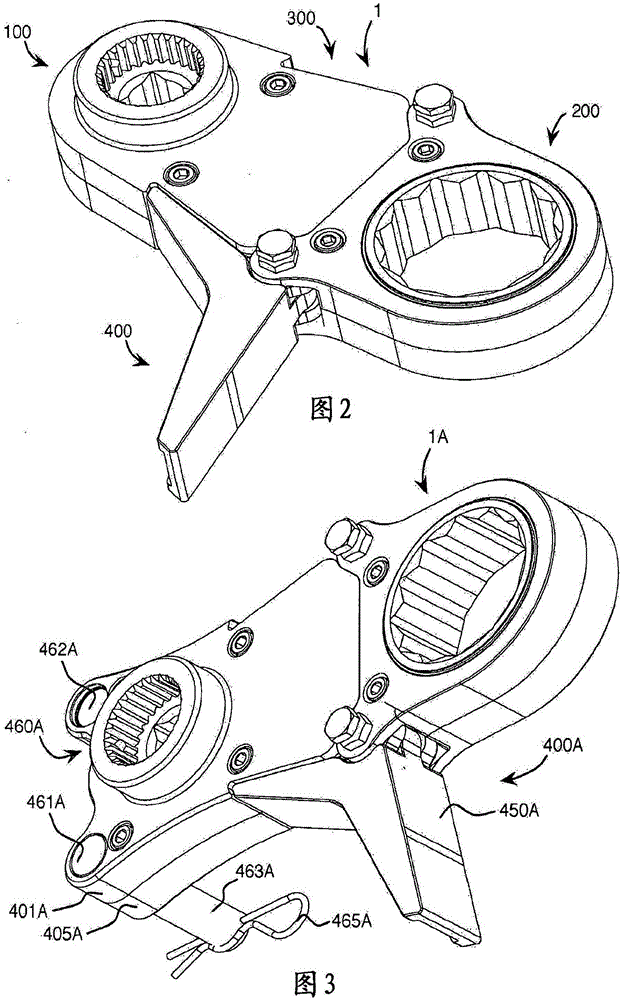
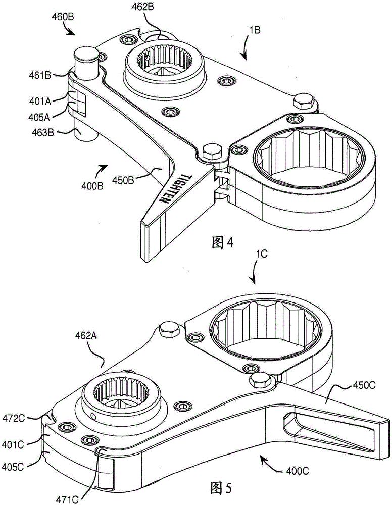
[0022] For example, refer to figure 1 A and 1B, there are shown perspective views of an embodiment of the invention as non-reaction arm apparatus 1A and 1B for tightening and loosening industrial threaded fasteners 20 with minimal galling, such The industrial threaded fastener 20 has a nut 21 , a washer 22 and a stud 23 . Devices 1A and 1B include: drive input and output assembly 100 ; rotational force multiplication assembly 200 ; vibratory force assembly 300 ; mode conversion assembly 400 ;

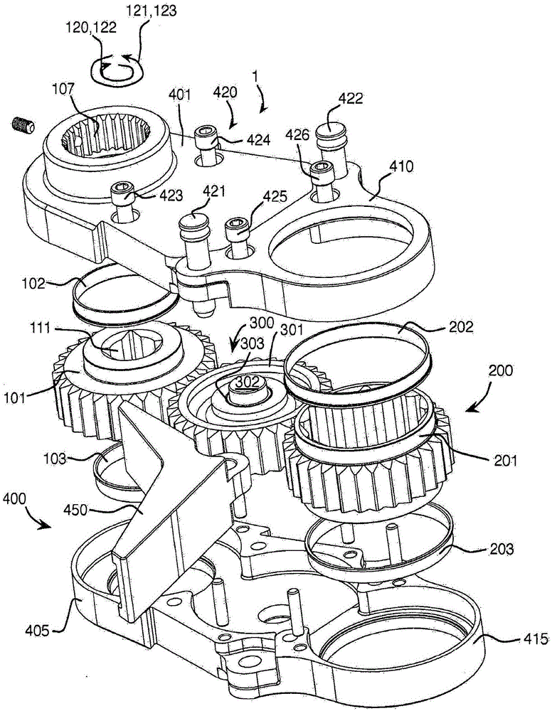
[0023] For example, refer to figure 1 , which shows an exploded perspective view of an embodiment of the present invention in the form of an apparatus 1 or offset drive linkage assembly 1 for delivering and increasing input from means for tightening or loosening threaded fasteners (not shown) ( not shown) torque. The device 1 includes: a driving force input assembly 100 ; a driving force output assembly 200 ; and a reaction force assembly 400 . The apparatus 1 also includes a drive ...


PUM


Abstract

An offset drive link assembly for transmission and multiplication of torque from a power tool for tightening or loosening a threaded fastener includes: a drive force input assembly; a drive force output assembly; and a reaction force assembly. Advantageously the offset drive link assembly: allows access to previously unreachable fasteners due to, for example protruding threads, limited clearances and obstructions; makes practical previously unusable devices driven either electrically, hydraulically, manually and/or pneumatically; makes feasible previously unusable advanced materials, such as, for example aircraft-grade aluminum; creates modular components, such as, for example hex-reducing and -increasing drive bushings, male to female drive adaptors, to meet bolting application characteristics; yields accurate and customizable torque multiplication; tames drive force and reaction force application; overcomes corrosion, thread and facial deformation; avoids bolt thread galling; nullifies side load; ensures balanced bolt load for symmetrical joint compression; simplifies link and tool use; minimizes risk of operator error; and maximizes bolting safety.

Description

[0001] Cross References to Related Applications [0002] This application is a continuation or continuation-in-part of the following commonly owned and co-pending patent application, which is incorporated herein by reference in its entirety: U.S. Patent Application No. 61 / 815,428, filed April 24, 2013, Titled "APPARATUSFORTIGHTENINGTHREADEDFASTENERS"; U.S. Patent Application No. 61 / 903254, filed December 12, 2013, titled "APPARATUSFORTIGHTENINGTHREADEDFASTENERS"; U.S. Patent Application No. 61 / 916926, filed December 17, 2013, Titled "APPARATUSFORTIGHTENINGTHREADEDFASTENERS"; and U.S. Patent Application No. 61 / 940919, filed February 18, 2014, entitled "APPARATUSFORTIGHTENINGTHREADEDFASTENERS." [0003] The new technology disclosed in this application advances the technology disclosed in the following commonly-owned issued patents and patent applications, which are incorporated herein by reference in their entirety, including: U.S. Patent No. 5,140,874, published August 25, 1992 ...

Claims


Application Information

Patent Timeline
Patent Type & Authority Applications(China)
IPC IPC(8): B25B13/48B25B17/00B25B17/02B25B23/00
CPCB25B17/00B25B17/02B25B23/0078B25B13/481B25B7/10
Inventor J·K·琼克斯P·克彭赫弗
Owner HYTORC DIV UNEX CORP
Why Eureka
Try Eureka