Seat cushion frame structure of seat for vehicle and seat for vehicle with seat cushion frame structure

a seat cushion and seat back frame technology, which is applied in the direction of chairs, pedestrian/occupant safety arrangements, vehicular safety arrangements, etc., can solve the problems of increased weight of seat back frame structure, high strength member is so expensive, and seat for a vehicle costs mor

Inactive Publication Date: 2013-02-12
NHK SPRING CO LTD
View PDF10 Cites 55 Cited by
  • Summary
  • Abstract
  • Description
  • Claims
  • Application Information

AI Technical Summary

Benefits of technology

[0011]In view of the above technical problems, an object of the present invention is to provide a seat cushion frame structure of a seat for a vehicle and a seat for a vehicle with such a seat cushion frame structure which are capable of securing a necessary strength or rigidity, while at the same time attaining a decrease in the weight and cost of a seat.
[0013]According to the seat cushion frame structure of a seat for a vehicle of the present invention, based on the fact that, with respect to a supposed impact load loaded on a seat back frame structure, the impact load toward the rear side of the vehicle is set to be higher than that toward the front side of the vehicle, a sectional shape of at least one of a pair of side frames can be determined so as to set a section modulus of at least one of the pair of side frames in such a way that at least one of the pair of side frames can withstand a bending moment caused by the impact load loaded toward the front side of the vehicle, and in a case where the impact load is loaded toward the rear side of the vehicle, when such an impact load is transmitted to the seat cushion frame structure through a connection portion between the seat cushion and the seat back, it is possible to cause an oblique wire to share a difference between said impact load toward the front side of the vehicle and that toward the rear side of the vehicle by positioning the oblique wire so as to cause a tension force from the oblique wire to be exerted on the seat cushion frame structure in such a way that said bending moment acting on the seat cushion frame structure based on said impact load toward the rear side of the vehicle can be alleviated.
[0015]Since it becomes unnecessary to set a sectional shape of the pair of side frames so as to withstand the impact load toward the rear side of the vehicle, a necessary strength or rigidity can be secured, while at the same time the weight of the pair of side frames can be decreased by means of the oblique wire.
[0034]According to the seat for the vehicle of the present invention, in a case where the seat for the vehicle is completed by mounting a pad on the above frame structure of the seat for the vehicle, the embedding of the oblique wire into the pad can prevent a visual appearance of the seat for the vehicle from being deteriorated.

Problems solved by technology

However, said conventional seat back frame structure has caused the following technical problems.
The strength or the rigidity of the seat back frame structure can be improved by the closed sectional structure (a box structure) of the seat back frame structure and the provision of the energy absorbing portion, however, the increase of the weight of the seat back frame structure is caused.
However, such a high strength member is so expensive that the seat for a vehicle costs more, even if the increase of the weight can be restricted.
However, like the seat back frame structure, in order to secure the strength or the rigidity, the weight of the seat cushion frame structure is inevitably increased, and its cost is also increased if the high tension member is adopted.

Method used


Image

  • Seat cushion frame structure of seat for vehicle and seat for vehicle with seat cushion frame structure
  • Seat cushion frame structure of seat for vehicle and seat for vehicle with seat cushion frame structure
  • Seat cushion frame structure of seat for vehicle and seat for vehicle with seat cushion frame structure

Examples


Embodiment Construction

[0062]The embodiment of the present invention in which the seat for the vehicle is applied to a front seat of an automobile will be described in detail with reference to the drawings as an example.

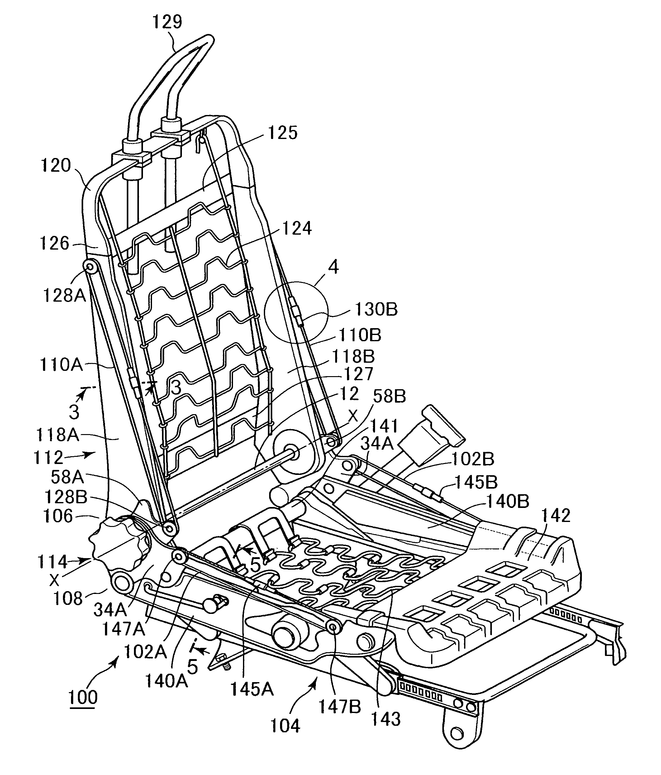
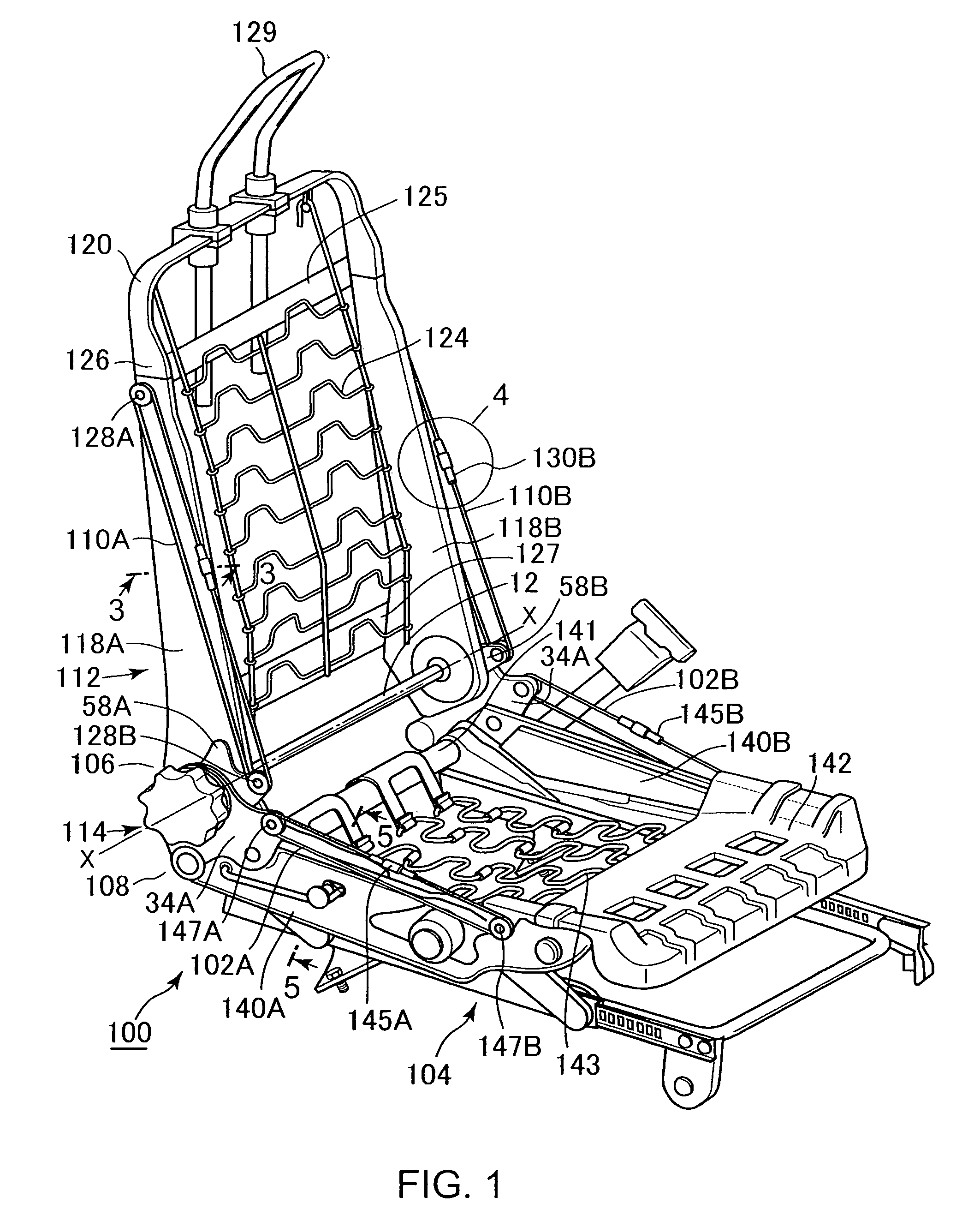
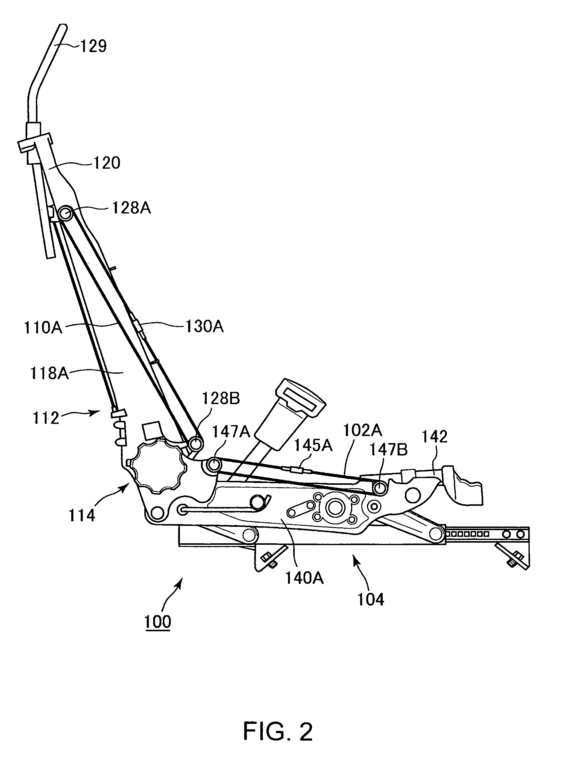
[0063]As shown in FIGS. 1 and 2, a seat 100 for a vehicle of the present invention comprises a seat cushion frame structure 104 portion 104 which is fixed on a floor of a vehicle compartment and includes oblique wires 102A,B described hereinafter, a seat back frame structure 112 portion 112 a lower end portion 106 of which is connected to a rear end portion 108 of the seat cushion frame structure 104 portion 104 so as to be inclined relative thereto and which includes oblique wires 110A,B described hereinafter, a recliner structure portion 114 interposed between the seat cushion frame structure 104 portion 104 and the seat back frame structure 112 portion 112, a pad (not shown) so as to cover the entire seat frame structure for the vehicle, and a skin sheet (not shown) so as to cover the e...


PUM


Abstract

A seat cushion frame structure of a seat for a vehicle has a seat cushion frame structure, a rear end of which is connected to a lower end of a seat back frame structure in such a way that the seat back frame structure can be inclined relative to the seat cushion frame structure, the seat cushion frame structure includes a pair of side frames, each of which extends in a longitudinal direction of the vehicle, and an oblique wire on at least one of the pair of side frames, an upper end of which is fixed to a side portion of the at least one of pair of side frames and a lower end of which is fixed to the seat cushion frame structure at a position forward of the upper end.

Description

FIELD OF THE INVENTION[0001]The present invention relates to a seat cushion frame structure of a seat for a vehicle and a seat for a vehicle with said seat cushion frame structure, and, in particular, relates to such a seat cushion frame structure of a seat for a vehicle and a seat for a vehicle with said seat cushion frame structure which are capable of decreasing the cost and weight of a seat, while at the same time securing a necessary strength or rigidity.BACKGROUND OF THE INVENTION[0002]Conventionally, a seat back frame structure of a seat for a vehicle which is capable of reducing an impact load acting on a passenger has been adopted. The Japanese Patent Laid-open Publication HEI11-32865, for instance, discloses one example of such a seat back frame structure.[0003]This seat back frame structure for a vehicle comprises a seat back frame structure integrally formed into a substantially C-shape, a tubular body connecting right and left longitudinal frames of the seat back frame ...

Claims


Application Information

Patent Timeline
Patent Type & Authority Patents(United States)
IPC IPC(8): A47C7/02B60N2/90
CPCB60N2/2356B60N2/68B60N2/4228B60N2/236
Inventor NONOMIYA, MASAAKI
Owner NHK SPRING CO LTD
Why Eureka
Try Eureka