Check patentability & draft patents in minutes with Patsnap Eureka AI!

Light emitting device including resin and manufacturing method for the same

a technology of light-emitting devices and resins, which is applied in the manufacturing of semiconductor/solid-state devices, semiconductor devices, electrical devices, etc., can solve the problems of increasing manufacturing processes and driving up costs, unable to achieve desired optical properties, and unable to achieve desired heat resistance and resin strength

Active Publication Date: 2013-02-12
STANLEY ELECTRIC CO LTD
View PDF8 Cites 2 Cited by
  • Summary
  • Abstract
  • Description
  • Claims
  • Application Information

AI Technical Summary

Benefits of technology

[0010]In order to achieve the above object, the present invention provides a light emitting device including a light emitting element, and a resin part arranged at a position which light emitted from the light emitting element passes through, wherein the resin part has a configuration including a sea-island structure formed by mixing two or more types of materials being immiscible. Since the sea-island structure is formed in this manner, light is scattered on the interface between a sea part and an island part. Therefore, it is possible to deliver a scattering property even if an encapsulant is manufactured according to a simple process.
[0012]Both of the sea part and the island part of the sea-island structure may be made of a polymer material. By way of example, it is preferable that both of the polymer materials which constitute the sea part and the island part respectively are silicone resin, because the silicone resin is able to enhance durability. One of the silicone resins constituting the sea part and the island part respectively is allowed to introduce a hydrocarbon group into the side chain, thereby establishing immiscibility.
[0014]Either of the resin constituting the sea part and the polymer material constituting the island part serves as a base resin, and a curing agent to cure the base resin can be used as the other. Accordingly, it is possible to easily form an encapsulant made of resin as a whole.
[0016]It is preferable that both materials constituting the sea part and the island part of the sea-island structure are transparent against visible light. This is because transmittance can be maintained, while delivering the scattering property.
[0020]It is preferable to employ silicone resin materials for both of the two types of immiscible liquid materials, because such materials may enhance the durability of the light emitting device. One of the silicone resin materials of the two types of immiscible materials is allowed to introduce hydrocarbon-based substituent in the side chain, thereby facilitating establishment of immiscibility.
[0024]According to the present invention, it is possible to provide a light emitting device which is manufactured in a simple process of mixing two materials, and which includes a resin delivering a desired scattering property.

Problems solved by technology

In the techniques described in the patent documents 1 to 4 where particles are dispersed in a resin, it is necessary to prepare in advance particles being tiny in diameter, made of an inorganic material or an organic material, and it may cause a more complicated manufacturing process and drive up costs.
There is another problem that when fine particles are dispersed in the resin as described in the patent documents 1 to 4, following situations may be found; coagulation of fine particles resulting in formation of secondary particles, inhomogeneous dispersion of the fine particles, or occurrence of sedimentation.
In such instances above, there is a possibility that a desired optical property is not obtained, and further, a desired heat resistance and resin strength may not be obtained either.
If the fine particles of inorganic material are added as disclosed in the patent documents 1, 3, and 4, Young's modulus of an encapsulation resin becomes higher along with the increase of contained amount of the fine particles of inorganic material, and consequently separation and / or cracks may occur.
In addition, there is a possibility that thermal expansion caused by heat shock may break a feed wire.

Method used


Image

  • Light emitting device including resin and manufacturing method for the same
  • Light emitting device including resin and manufacturing method for the same
  • Light emitting device including resin and manufacturing method for the same

Examples


example 1

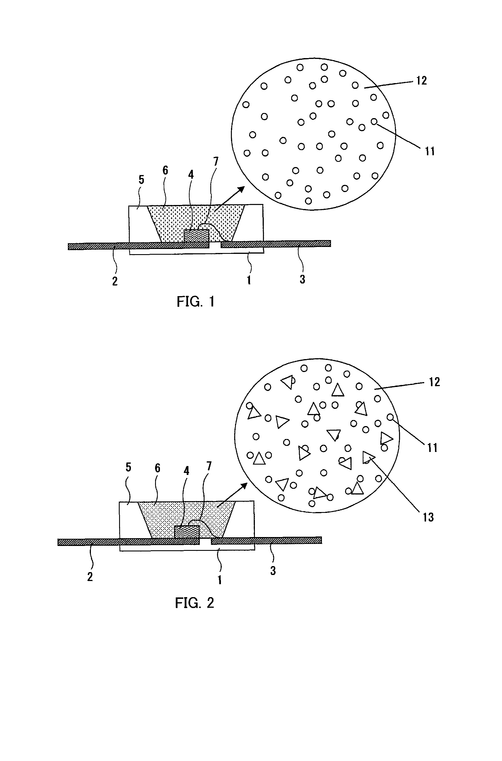
[0054]In the example 1, an encapsulant 6 was formed by mixing two types of immiscible resin materials (base resin and curing agent).

[0055]Firstly, the substrate 1 on which the electrodes 2 and 3 were formed was prepared, and die-bonding of the LED chip 4 onto the electrode 2 was performed. Wire-bonding of both ends of the wire 7 respectively onto the upper surface electrode of the LED chip 4 and the electrode 3 was performed, thereby establishing connection therebetween. The package 5 was fixed around the LED chip 4.

[0056]Next, 0.3759 g of polystyrene (a product of Sigma-Aldrich Japan Co.) as a base resin, 0.25 g of U-6LPA (a product of Shin-Nakamura Chemical Co., Ltd.) and 0.0625 g of APT022 (a product of Shin-Nakamura Chemical Co., Ltd.) as curing agents, and 0.0156 g of Darocur 1173 (a product of Chiba Specialty Chemicals K. K.) as a polymerization initiator were dissolved into 25 ml of THF (tetrahydrofuran).

[0057]Coating of the resin material composition being obtained was appli...

example 2

[0059]In the example 2, a resin material composition was obtained by mixing silicone oil in a silicone resin, and the light emitting device as shown in FIG. 2 was produced.

[0060]To obtain the resin material composition, silicone resin OE6665A, B (a product of Dow Corning Toray Co., Ltd.) and 8% of silicone oil KF351 (a product of Shin-Etsu Chemical Co., Ltd.) were mixed. In here, 8 wt % of YAG-based phosphor particles were mixed as the phosphor particles 13. An LED chip which emits blue light was employed as the LED chip 4.

[0061]Coating of the resin material composition being obtained was applied to the LED chip 4, and a coated film was formed by evaporating the solvent at a room temperature. After heating at 150° C. for sixty minutes, UV rays were irradiated on the coated film, thereby curing the film. Other steps were carried out in the same manner as the example 1.

[0062]The resin material compositions as observation samples were obtained by varying the mixed quantity of the silic...


PUM

PropertyMeasurementUnit
particle diameteraaaaaaaaaa

Abstract

A light emitting device is provided, including a resin which can be manufactured according to a simple process and deliver a desired scattering property. The light emitting device is manufactured according to a step for mixing two or more types of immiscible liquid materials to obtain a composition containing at least two types of materials phase-separated in a sea-island structure, and a step for arranging the composition in proximity to an LED chip, curing the composition with the sea-island structure being maintained, thereby forming an encapsulation resin. Accordingly, it is possible to form an island region which serves as a scattering center, according to a simple step of mixing materials.

Description

FIELD OF THE INVENTION[0001]The present invention relates to a light emitting device provided with a resin part which causes a scattering of light from a light emitting element.DESCRIPTION OF THE RELATED ART[0002]By way of example, there is known a light-emitting element which encapsulates an LED chip in a transparent resin so as to enhance efficiency in retrieving light from the LED chip, as described in the Japanese Unexamined Patent Application Publication No. 2007-308345 (hereinafter, referred to as “patent document 1”) and the like. It is disclosed that in the structure above, crystalline grains of metal oxide are dispersed in the transparent resin, thereby increasing the refractive index of the transparent resin, while keeping strength of the resin, and accordingly, the light retrieval efficiency is enhanced and light scattering properties are delivered as well.[0003]The Japanese Unexamined Patent Application Publication No. 2007-269999 (hereinafter, referred to as “patent doc...

Claims


Application Information

Patent Timeline
Patent Type & Authority Patents(United States)
IPC IPC(8): H01L33/00
CPCH01L33/56H01L33/501H01L2933/0091H01L2224/48091H01L2224/48247H01L2924/181H01L2924/00012H01L2924/00014
Inventor KUMEI, MASAMIOWADA, SOJITAKAYAMA, KOICHIHARADA, MITSUNORI
Owner STANLEY ELECTRIC CO LTD
Features
  • R&D
  • Intellectual Property
  • Life Sciences
  • Materials
  • Tech Scout
  • Unparalleled Data Quality
  • Higher Quality Content
  • 60% Fewer Hallucinations
Learn More