RFID transponder using ambient radiation

a transponder and ambient radiation technology, applied in the field of transponders, can solve the problems of limited tag life to the life of the battery, inability to access the tag for many applications, and inability to achieve the effect of many applications

Active Publication Date: 2013-02-12
RADIOFIDO
View PDF17 Cites 21 Cited by
  • Summary
  • Abstract
  • Description
  • Claims
  • Application Information

AI Technical Summary

Problems solved by technology

In many environments this is neither feasible nor desirable.
While active RFID tags respond using energy derived from a battery on the tag, this limits tag life to the life of the battery or requires access to the tag to replace batteries as they drain.
Tag access is not feasible or possible for many applications.
This limits the range over which tags can operate and can cause interference when interrogation signals are at higher powers.
Similarly, sensors that wirelessly communicate their data are limited in range and lifespan.

Method used


Image

  • RFID transponder using ambient radiation
  • RFID transponder using ambient radiation
  • RFID transponder using ambient radiation

Examples


embodiment 100

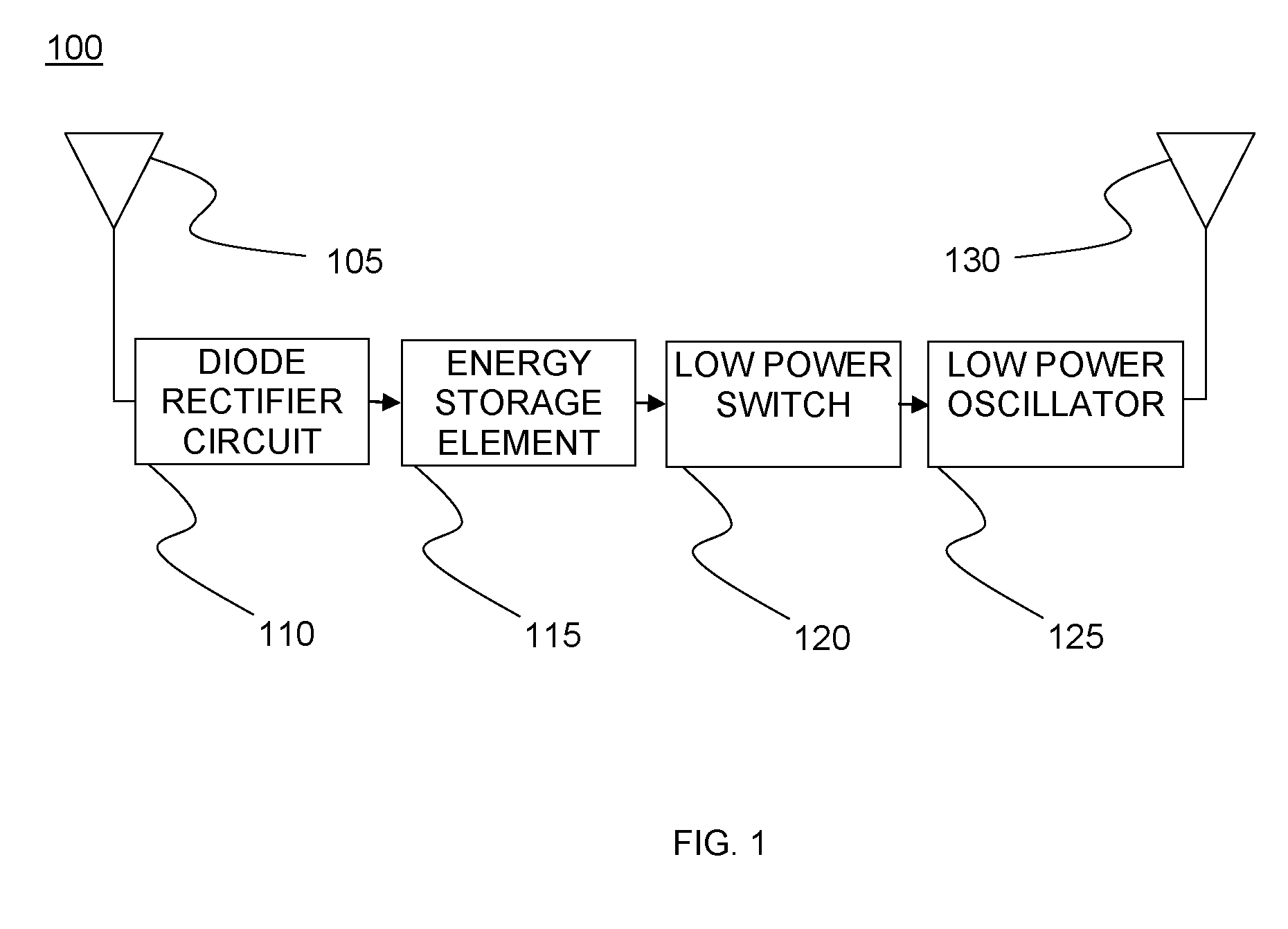
[0024]FIG. 1 illustrates embodiment 100 of an RFID transponder that operates off of ambient radiation. The antenna 105 receives RF power from the environment. The diode rectifier 110 is a high efficiency diode rectifier circuit that converts nano-watt levels of received RF power to milli-volt levels of DC voltage. The DC power is stored in the energy storage element 115. Once the energy storage element 115 is charged to a pre-defined level, the hysteretic switch 120 will discharge the energy to the low power oscillator 125. Low power oscillator 125 operates off of low voltage levels to produce micro-watts of transmit power. The microwatts of power generated from nano-watt levels of received RF energy is transmitted via antenna 130. An optional low current (nanoamps) charging path and small battery may be added to the energy storage element 115, allowing for a low duty cycle mode of operation. Battery power consumption is sufficiently low that the battery will last for essentially it...

embodiment 200

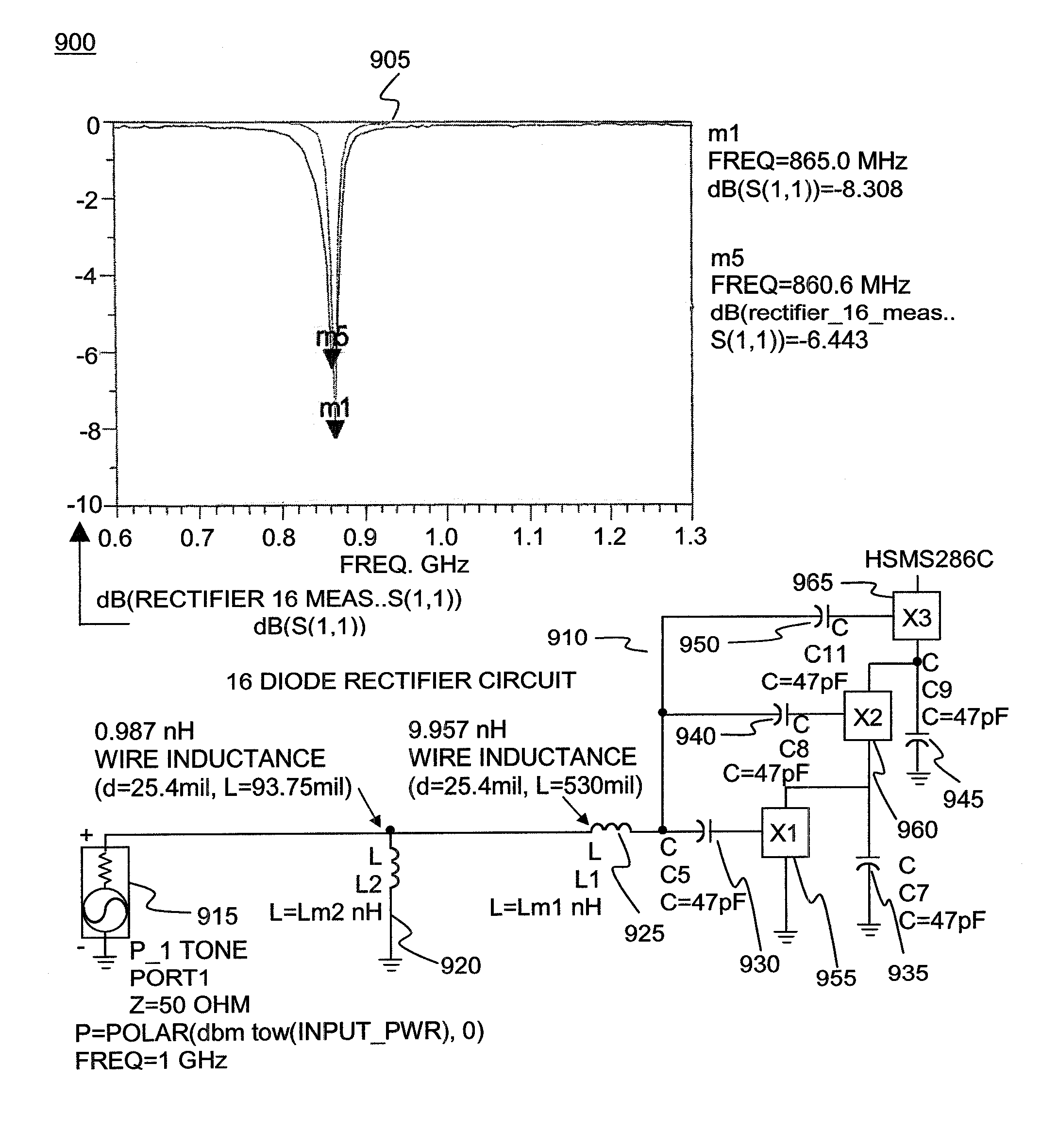
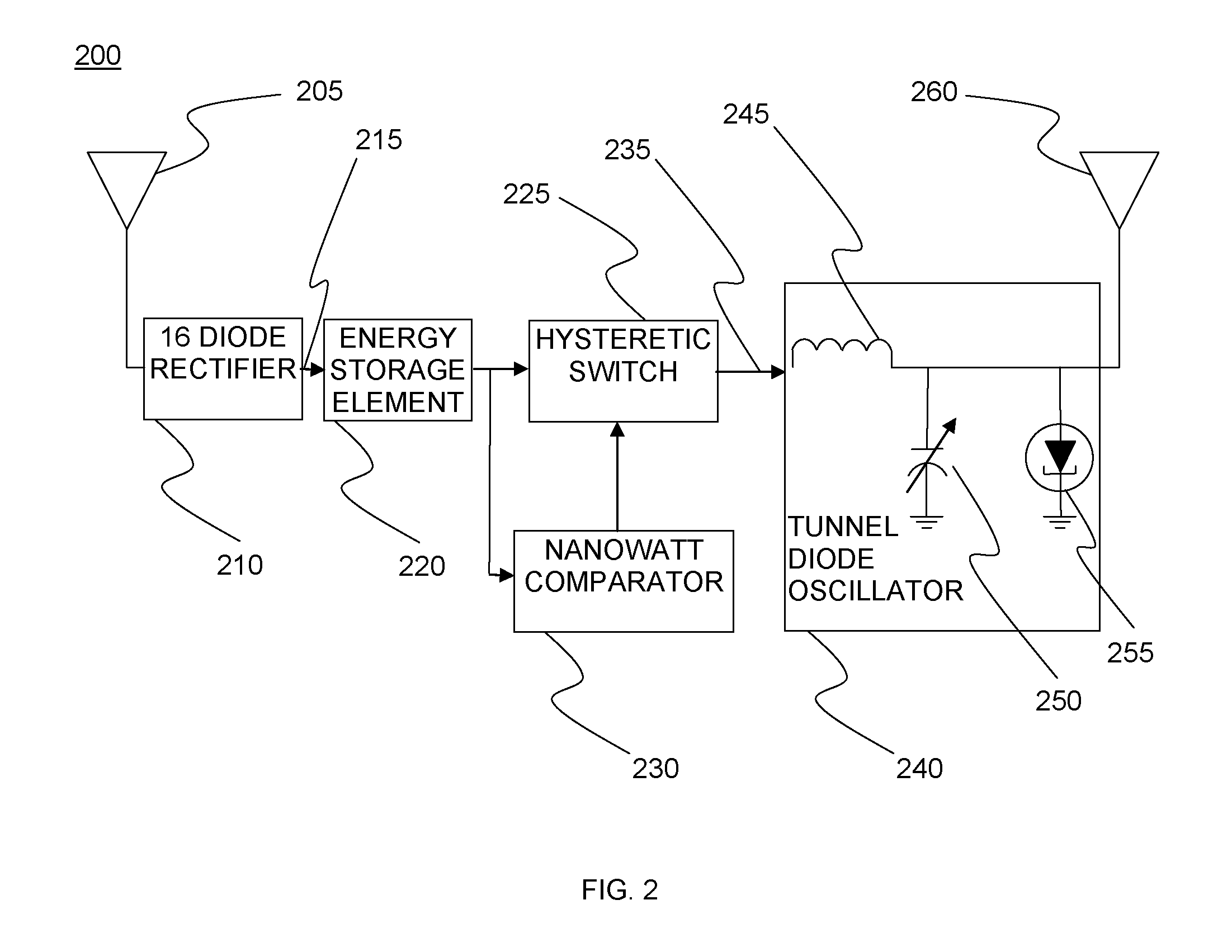
[0025]FIG. 2 depicts embodiment 200 with receive antenna 205 operating at 831 MHz −28 to −38 dBm. For nonlimiting embodiments, 160 to 1600 nW activate the tag. Sixteen diode rectifier 210 has output 215 of 50 to 400 millivolts to energy storage element 220. Energy storage element 220 comprises 1 to 10 microFarad capacitance (1.3 nJ to 80 nJ of stored energy), with E=½ (CV2), taking 160 to 1,600 mS to charge and 40 to 800 mS to discharge. Energy storage element 220 output is provided to hysteretic switch 225 and nanowatt comparator 230. Nonlimiting embodiment examples include a Maxim® MAX9027 at 1.8 volts at 450 nA. Maxim is a registered trademark of Maxim Integrated Products, Inc. Output of switch 225 is 235 50 to 200 millivolts. Switch 225 output 235 is applied to tunnel diode oscillator 240. Tunnel diode oscillator 240 operates at 50 to 200 micro watts (65 millivolts at 1 milliamp, typical) and comprises inductor 245, Micro-Electro-Mechanical Systems (MEMS) sensor 250, and tunnel ...

embodiment 1100

[0035]FIG. 11 provides data for an embodiment 1100 of a hysteretic switch. Active hysteresis switch waveform 1105 provides Cap and Switch out results for −2 to +2 seconds over −0.5 to +2.5 volts. Active hysteresis switch waveform 1110 provides Cap and Switch out results for −0.005 to +0.005 seconds over −0.5 to +2.5 volts. Active hysteresis switch positive edge switching time (50 Ohm load) 1115 provides Cap and Switch out results for −40 to +40 nanoseconds over −0.5 to +2.5 volts. Active hysteresis switch negative edge switching time (50 Ohm load) 1120 provides Cap and Switch out results for −40 to +40 nanoseconds over −0.5 to +2.5 volts. In embodiments, the hysteretic switch trickle charges batteries and or capacitors. Properties are derived from the input voltage level. Employing a hysteretic switch plus low-power components enables use of very small devices.

Method

[0036]FIG. 12 is a flow chart depicting a method 1200 for a transponder using ambient radiation. Ambient radiation is ...


PUM


Abstract

A tag operates in an environment where transmitted interrogators are not possible or desired. High-efficiency diode rectifiers and low-power oscillators are used in combination with an energy storage element and hysteretic switch. The combination of multi-diode rectifier, low power tunnel diode oscillator, energy storage element and hysteretic switch allow for nanowatt levels of received RF power to be stored to produce micro-watts of RF transmit power. The device trickle charges off of ambient RF radiation until enough energy is stored for transmission.

Description

FIELD OF THE INVENTION[0001]The invention relates to ambient radiation power scavenging, and more particularly, to a transponder using rectifiers and oscillators in combination with an energy storage element and switch.BACKGROUND OF THE INVENTION[0002]Existing transponder devices such as Radio Frequency IDentification (RFID) tags require either a self-contained power supply, RF energy transmitted from an interrogator, or both to operate. This typically requires close proximity to the interrogator or higher-power RF transmissions. In many environments this is neither feasible nor desirable.[0003]While active RFID tags respond using energy derived from a battery on the tag, this limits tag life to the life of the battery or requires access to the tag to replace batteries as they drain. Tag access is not feasible or possible for many applications. Passive tags not require batteries, but do require RF interrogation signals of sufficient power and duration to enable them to generate the ...

Claims


Application Information

Patent Timeline
Patent Type & Authority Patents(United States)
IPC IPC(8): H04Q5/22
CPCG06K19/0707G06K19/0723H04Q2213/13095
Inventor BROMMER, KARL D.BRITTAIN, CANDICE L.SUTPHIN, ELDON M.
Owner RADIOFIDO
Why Eureka
Try Eureka