Low friction tape head and system implementing same

Inactive Publication Date: 2013-02-12
INT BUSINESS MASCH CORP
View PDF50 Cites 28 Cited by
  • Summary
  • Abstract
  • Description
  • Claims
  • Application Information

AI Technical Summary

Problems solved by technology

However, the development of higher performance tape drive systems has created various problems in the design and manufacture of a tape head assembly for use in such systems.

Method used


Image

  • Low friction tape head and system implementing same
  • Low friction tape head and system implementing same
  • Low friction tape head and system implementing same

Examples


embodiment 400

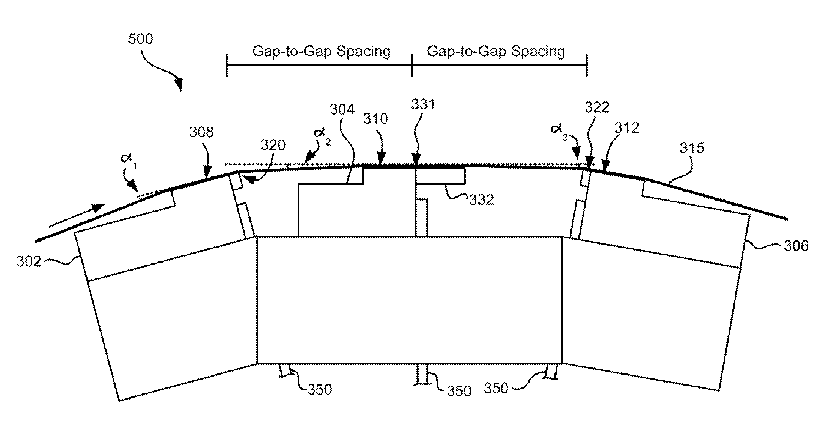
[0047]Depending on tape tension and stiffness, it may be desirable to angle the tape bearing surfaces of the outer modules relative to the tape bearing surface of the second module. FIG. 4 illustrates an embodiment 400 where the modules 302, 304, 306 are in a tangent (angled) configuration. Particularly, the tape bearing surfaces of the outer modules 302, 306 are about parallel to the tape at the desired wrap angle α2 of the second module 304. In other words, the planes of the tape bearing surfaces 308, 312 of the outer modules 302, 306 are oriented at about the desired wrap angle α2 of the tape 315 relative to the second module 304. The inventor has found that the tape will also pop off of the trailing module 306 in this embodiment, thereby reducing wear on the elements in the trailing module 306. These embodiments are particularly adapted for write-read-write applications. Additional aspects of these embodiments are similar to those given above.

[0048]Typically, the tape wrap angle...

embodiment 500

[0050]FIG. 5 illustrates an embodiment 500 where the modules 302, 304, 306 are in an overwrap configuration. Particularly, the tape bearing surfaces 308, 312 of the outer modules 302, 306 are angled slightly more than the tape 315 when set at the desired wrap angle α2 relative to the second module 304. In this embodiment, the tape does not pop off of the trailing module, allowing it to be used for writing or reading. Accordingly, the leading and middle modules can both perform reading and / or writing functions while the trailing module can read any just-written data. Thus, these embodiments are preferred for write-read-write, read-write-read, and write-write-read applications. In the latter embodiments, closures should be wider than the tape canopies for ensuring read capability. The wider closures will force a wider gap-to-gap separation. Therefore the preferred embodiment has a write-read-write configuration, which may use shortened closures that thus allow closer gap-to-gap separa...


PUM

PropertyMeasurementUnit
lengthaaaaaaaaaa
lengthaaaaaaaaaa
wrap angleaaaaaaaaaa

Abstract

A magnetic head according to one embodiment includes outer modules each having a tape bearing surface and an array of transducers selected from a group consisting of readers and writers; and an inner module positioned between the outer modules, the inner module having a tape bearing surface and an array of transducers selected from a group consisting of readers and writers, wherein portions of edges of the tape bearing surface of the inner module are non-skiving in regions not aligned with the array of transducers in a direction of media travel thereacross, wherein an outer edge of the tape bearing surface of each of the outer modules are adapted for skiving air from the magnetic medium when the magnetic medium travels in a direction from the respective outer module towards the inner module.

Description

BACKGROUND[0001]The present invention relates to magnetic tape storage systems, and more particularly, this invention relates to a low friction tape head.[0002]Business, science and entertainment applications depend upon computers to process and record data, often with large volumes of the data being stored or transferred to nonvolatile storage media, such as magnetic discs, magnetic tape cartridges, optical disk cartridges, floppy diskettes, or floptical diskettes. Typically, magnetic tape is the most economical and convenient means of storing or archiving the data. Storage technology is continually pushed to increase storage capacity and storage reliability. Improvement in data storage densities in magnetic storage media, for example, has resulted from improved medium materials, improved magnetic read / write heads, improved error correction techniques and decreased areal bit sizes. The data capacity of half-inch magnetic tape, for example, is now measured in tens of terabytes (thou...

Claims


Application Information

Patent Timeline
Patent Type & Authority Patents(United States)
IPC IPC(8): G11B5/265
CPCG11B5/00826G11B5/60G11B5/1871G11B5/255G11B15/62G11B5/3106
Inventor BISKEBORN, ROBERT G.
Owner INT BUSINESS MASCH CORP
Why Eureka
Try Eureka