Method and implementation of in-situ absolute head medium spacing measurement

a technology of absolute head height and measurement method, which is applied in the direction of maintaining head carrier alignment, recording information storage, instruments, etc., can solve the problems of achieve negligible error of projected value of gap length and thickness of medium, the effect of minimizing the error of projected gap length

Inactive Publication Date: 2006-03-21
AGENCY FOR SCI TECH & RES
View PDF4 Cites 64 Cited by
  • Summary
  • Abstract
  • Description
  • Claims
  • Application Information

AI Technical Summary

Benefits of technology

[0007]The present invention provides a method that measures the absolute head-medium spacing when the head is at its normal flying status. The method includes encoding a code pattern on the magnetic medium; detecting a readback signal from the medium through the head, where any two harmonic signals can be isolated to extract amplitudes of the two harmonics; applying a series of computation to obtain a logarithmic ratio of the spacing loss-term of the harmonic signals to form a linear relationship with a testing frequency; and applying the linear relationship to compute the absolute head-medium spacing. The logarithmic ratio of the two harmonic amplitudes has a linear portion and a nonlinear portion, which is made up of a spacing loss-term, a gap loss-term and a thickness loss-term. The nonlinear portion is generated by nonlinear components of a gap loss-term and a thickness loss-term. The series of computation includes eliminating the nonlinear portion of the logarithmic ratio of the two harmonics and the linear components of the logarithmic ratio of the gap loss-term and the thickness loss-term such that only the spacing loss-term remains. The nonlinear portion of the logarithmic ratio of the harmonic amplitudes is eliminated through removal of the change in gradient of the logarithmic ratio of the harmonic amplitudes between consecutive test frequencies occurring over a test frequency range. To obtain the linear relationship of spacing loss-term versus testing frequency, the linear components of the logarithmic ratio of the gap loss-term and the thickness loss-term in relation to testing frequency are eliminated by applying known designed value of gap length of read head and thickness of media in a differentiated relationship between the logarithmic ratio of the harmonic amplitudes and test frequency. The linear component is eliminated at low frequency values to minimize error in the projected gap length of read head and the projected thickness of magnetic medium when compared to the actual gap length and medium thickness. At zero frequency, the gradients of the logarithmic ratios of the gap loss-term and the thickness loss-term are a constant. Therefore, when test frequencies are close to zero, the error of projected values of the gap length and thickness of the medium is negligible. From the spacing loss-term a linear relationship with the test frequency is established and through the gradient of the linear relationship, the absolute head medium spacing is deduced.
[0013]In one embodiment, the filter comprises an isolation unit for detecting the amplitude of any two harmonic signals at different frequencies while the computation unit computes the logarithmic ratio of amplitudes two harmonic signals by applying natural log on the ratio of the amplitudes. The two harmonic signals occur at different test frequencies such that one of the two is of a higher order. The signal processor is a digital signal processor (DSP) which includes an analog-to-digital unit, a temporary register for storing computed logarithmic ratio with the testing frequency, and a computation unit to eliminate the gap loss-term and thickness loss-term in order to find out the linear relationship of the spacing loss-term versus testing frequency.

Problems solved by technology

Therefore, when test frequencies are close to zero, the error of projected values of the gap length and thickness of the medium is negligible.

Method used


Image

  • Method and implementation of in-situ absolute head medium spacing measurement
  • Method and implementation of in-situ absolute head medium spacing measurement
  • Method and implementation of in-situ absolute head medium spacing measurement

Examples


example

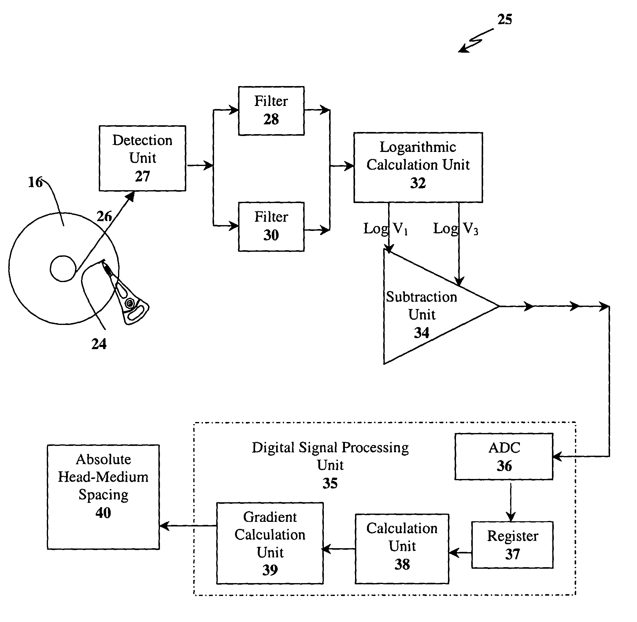
[0060]The following is an example to illustrate the present invention. A code pattern (111100) is pre-encoded on a magnetic disk surface. The preferred lower order harmonic and higher order harmonic are the first and third order harmonics, respectively, for this code pattern (i.e. n=3 and m=1). According to FIG. 11, this code is detected as a readback signal through the read head, which is then passed through filters for isolating the first and third harmonics. The ratio of the isolated harmonic amplitudes is calculated after the natural logarithms of the harmonic signals are tabulated in an algorithm in a digital signal processor (DSP) and the frequencies at which of these harmonics occur are registered. The gap loss-term and the thickness loss-term are removed by applying Equations (10) to (12) to establish the linear relationship of the logarithmic ratio of the spacing loss-term versus testing frequency and determining the gradient of the linear relationship to obtain the value o...


PUM

PropertyMeasurementUnit
optical wavelengthaaaaaaaaaa
frequencyaaaaaaaaaa
thicknessaaaaaaaaaa

Abstract

In a method based on readback signal for in-situ measuring of absolute head-medium spacing, a pre-encoded pattern in the magnetic medium on a disk has at least two harmonics with amplitudes such that a linear function of the logarithmic ratio of the spacing loss-term is formed in relation to testing frequencies. This linear function is applied to determine the absolute head-medium spacing directly through the multiplication of gradient of the linear function and the linear velocity between the head and the medium of the disk drive.

Description

TECHNICAL FIELD[0001]This invention relates to the flying height of a head in a disk drive. More particularly, it relates to a method of measuring the absolute spacing between the medium and the head directly in-situ from the readback signal and the implementation of the method through an apparatus for performing the method disclosed herein.BACKGROUND OF THE INVENTION[0002]In magnetic data storage devices, data information is stored and retrieved through the use of a magnetic transducer or head performing read and write operations on a magnetic medium. The transducer is also commonly referred to as a head. The magnetic head is deposited on a slider and positioned close to the surface of a disk where the magnetic materials are disposed forming the magnetic disk medium. The gap between the magnetic head and the surface of the magnetic disk medium is known as head-medium separation or magnetic separation. When the magnetic disk spins about the spindle on which it is mounted, the magnet...

Claims


Application Information

Patent Timeline
Patent Type & Authority Patents(United States)
IPC IPC(8): G11B27/36G11B21/02G11B21/21G11B5/00G11B5/58G11B5/60
CPCG11B5/58G11B21/21G11B5/6005G11B5/6029
Inventor LIU, BOYUAN, ZHIMIN
Owner AGENCY FOR SCI TECH & RES
Why Eureka
Try Eureka