Magnetic writer having a split yoke

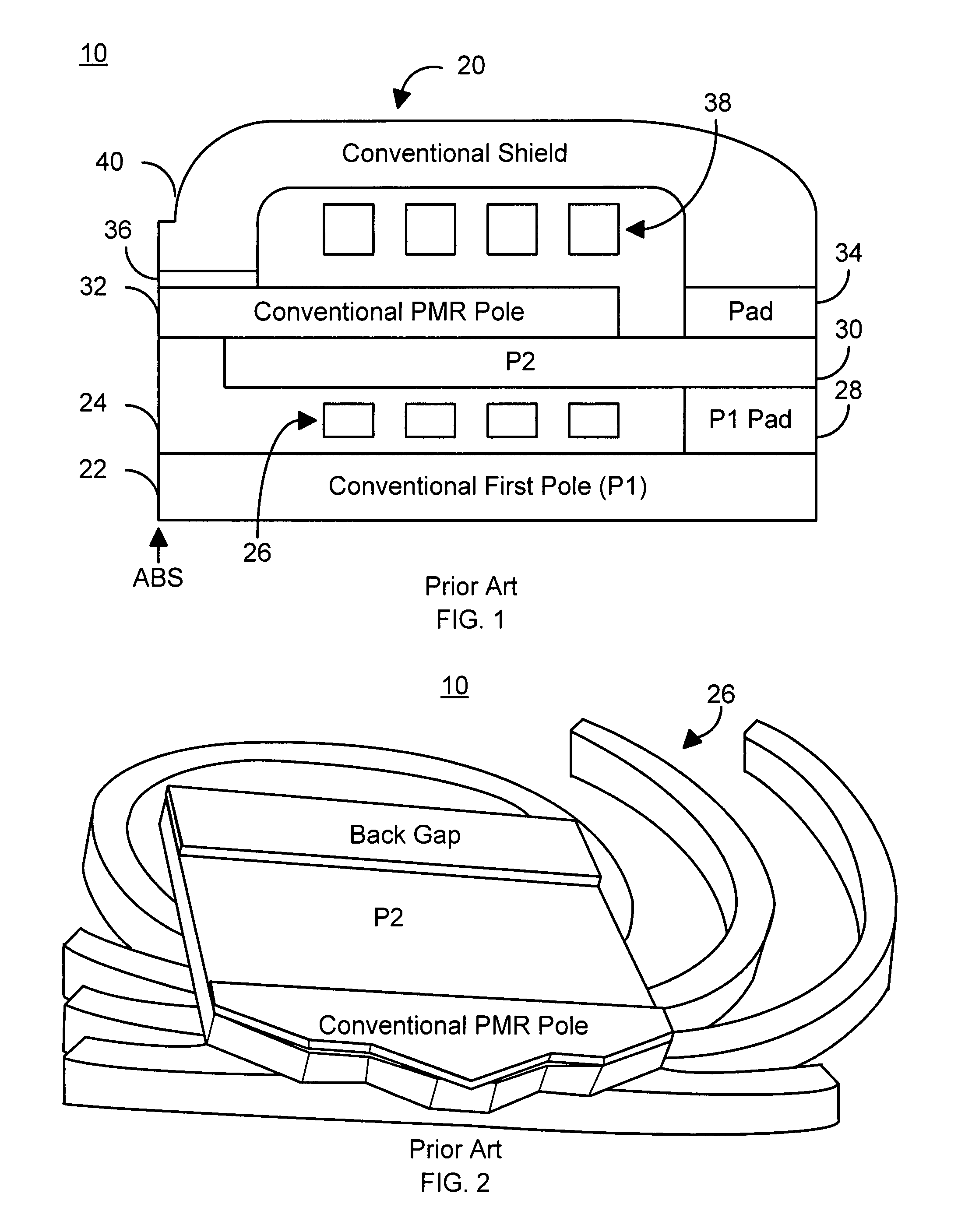
a writer and magnetic technology, applied in the field of magnetic writers, can solve the problems of adversely affecting write speed, adversely affecting disk drive reliability, and unsuitable for higher data rate use of conventional pmr heads b>10/b>,

Active Publication Date: 2013-02-12
WESTERN DIGITAL TECH INC
View PDF8 Cites 151 Cited by
  • Summary
  • Abstract
  • Description
  • Claims
  • Application Information

AI Technical Summary

Benefits of technology

[0009]FIG. 1 is a diagram depicting a side view of a conventional PMR write head.
[00

Problems solved by technology

Consequently, write speed may be adversely affected.
As a result, the conventional PMR head 10 may be unsuitable for use at higher data rates.
The conventional PMR head 10 may also be subject write pole tip protrusion, which adversely affects disk drive reliability.
This pole tip protrusion adversely impacts the reliability of disk drives usi

Method used


Image

  • Magnetic writer having a split yoke
  • Magnetic writer having a split yoke
  • Magnetic writer having a split yoke

Examples


Embodiment Construction

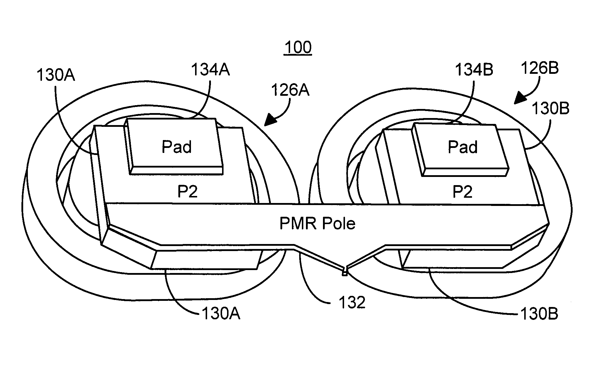
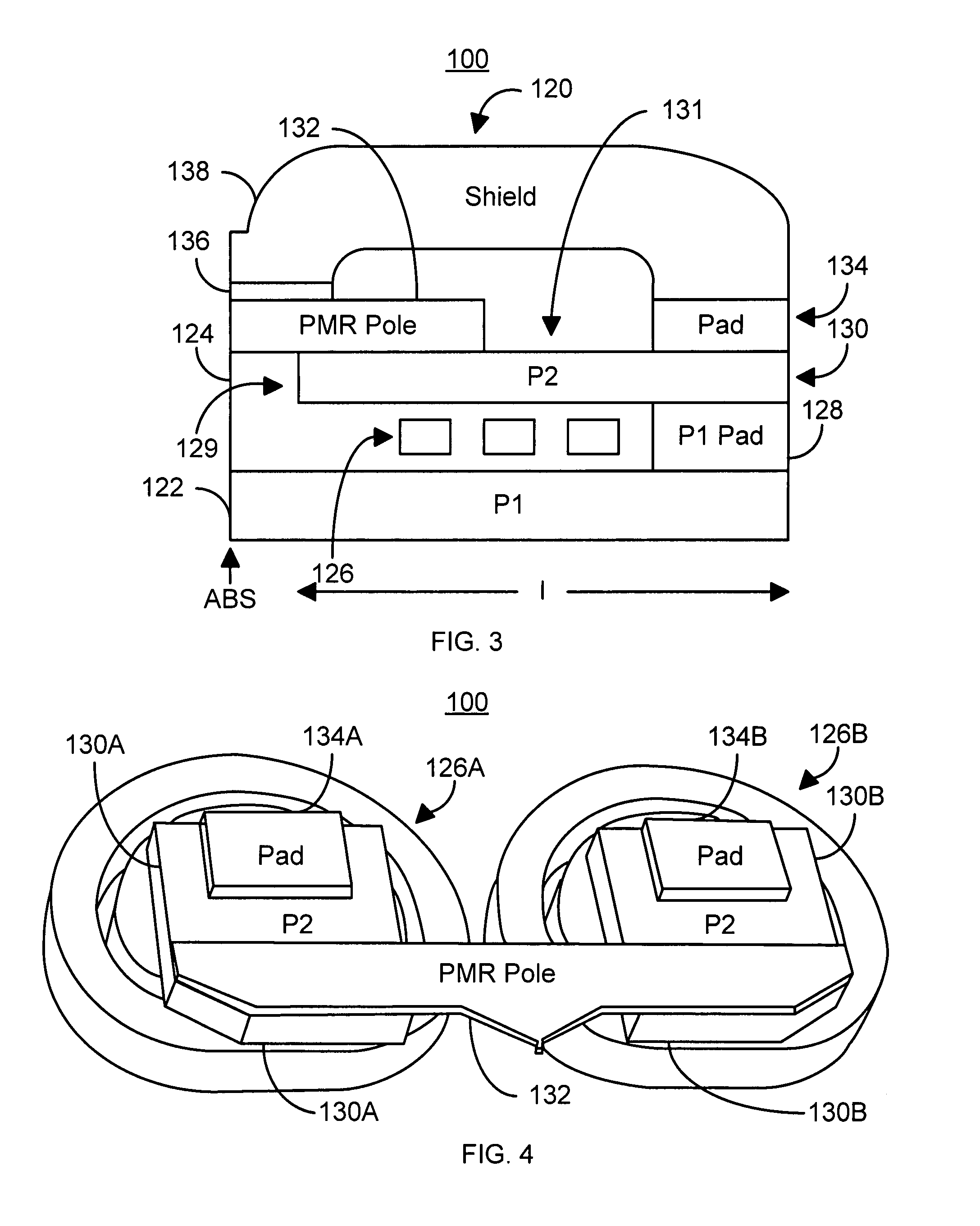
[0020]FIGS. 3 and 4 depict an exemplary embodiment of a portion of a PMR head 100. FIG. 3 is a side view of the PMR head 100, while FIG. 4 is a perspective view of the PMR head 100. For simplicity, only a write transducer 120 is depicted in FIG. 3 and only a portion of the write transducer 120 is depicted in FIG. 4. For clarity, FIGS. 3 and 4 are not drawn to scale. The PMR head 100 is preferably used as a write head in a merged head including at least the PMR head 100 and a read head (not shown).

[0021]The PMR head 100 includes a first pole P1122, insulator 124, a coil 126, optional P1 pad 128, a second pole P2130, the PMR write pole (or main pole) 132, write gap 136, an optional shield pad 134, and an optional shield 138. Although not explicitly shown, seed layer(s) may be used in providing the poles 122, 130, and 132. The PMR write transducer 120 is also depicted with a single split coil 126. However, in an alternate embodiment, the PMR head 100 may utilize an additional coil that...


PUM


Abstract

A method and system for providing a magnetic transducer are described. The magnetic transducer includes a first pole, a write gap, a second pole, a first coil, and a second coil. The first pole has a front portion on which at least a portion of the write gap resides. The second pole includes a split yoke that includes a first portion and a second portion. At least a portion of the first coil resides between the first portion of the split yoke and the first pole. At least a portion of the second coil resides between the second portion of the split yoke and the first pole.

Description

BACKGROUND[0001]In order to write data to and read data from a media, a recording head is typically used. FIGS. 1 and 2 depict side and perspective views of portion of a conventional perpendicular magnetic recording (PMR) head 10. For simplicity, only the write transducer 20 is shown in FIGS. 1 and 2. In addition, for clarity, FIGS. 1 and 2 are not drawn to scale. Although only the write transducer 20 is shown, the conventional write transducer 20 is generally part of a merged head that includes the transducer for writing, a read transducer for reading data from the media, and a slider. In addition, for clarity, only the conventional second pole (P2) 30 and the PMR write pole 32 are depicted in FIG. 2.[0002]The conventional PMR head 10 includes a conventional first pole (P1) 22, insulator 24, a first coil 26, P1 pad 28, the conventional P230, the conventional PMR write pole (or main pole) 32, insulator 24, write gap 36, a shield pad 34, a second coil 38, and shield 40. The conventio...

Claims


Application Information

Patent Timeline
IPC IPC(8): G11B5/31G11B5/17
CPCG11B5/1278G11B5/3123
Inventor LUO, PENGBAI, ZHIGANGWANG, YUGANGSTOEV, KROUM S.LIU, FRANCIS H.
Owner WESTERN DIGITAL TECH INC
Why Eureka
Try Eureka