Method for manufacturing a magnetic recording transducer having side shields

Active Publication Date: 2014-05-13
WESTERN DIGITAL TECH INC
View PDF78 Cites 140 Cited by
  • Summary
  • Abstract
  • Description
  • Claims
  • Application Information

AI Technical Summary

Problems solved by technology

Although this method functions at lower recording densities, at higher recording densities issues arise.
Consequently, at higher densities, the width of the conventional PMR pole may be sufficiently small that the conventional PMR pole collapses.
This may

Method used


Image

  • Method for manufacturing a magnetic recording transducer having side shields
  • Method for manufacturing a magnetic recording transducer having side shields
  • Method for manufacturing a magnetic recording transducer having side shields

Examples


Embodiment Construction

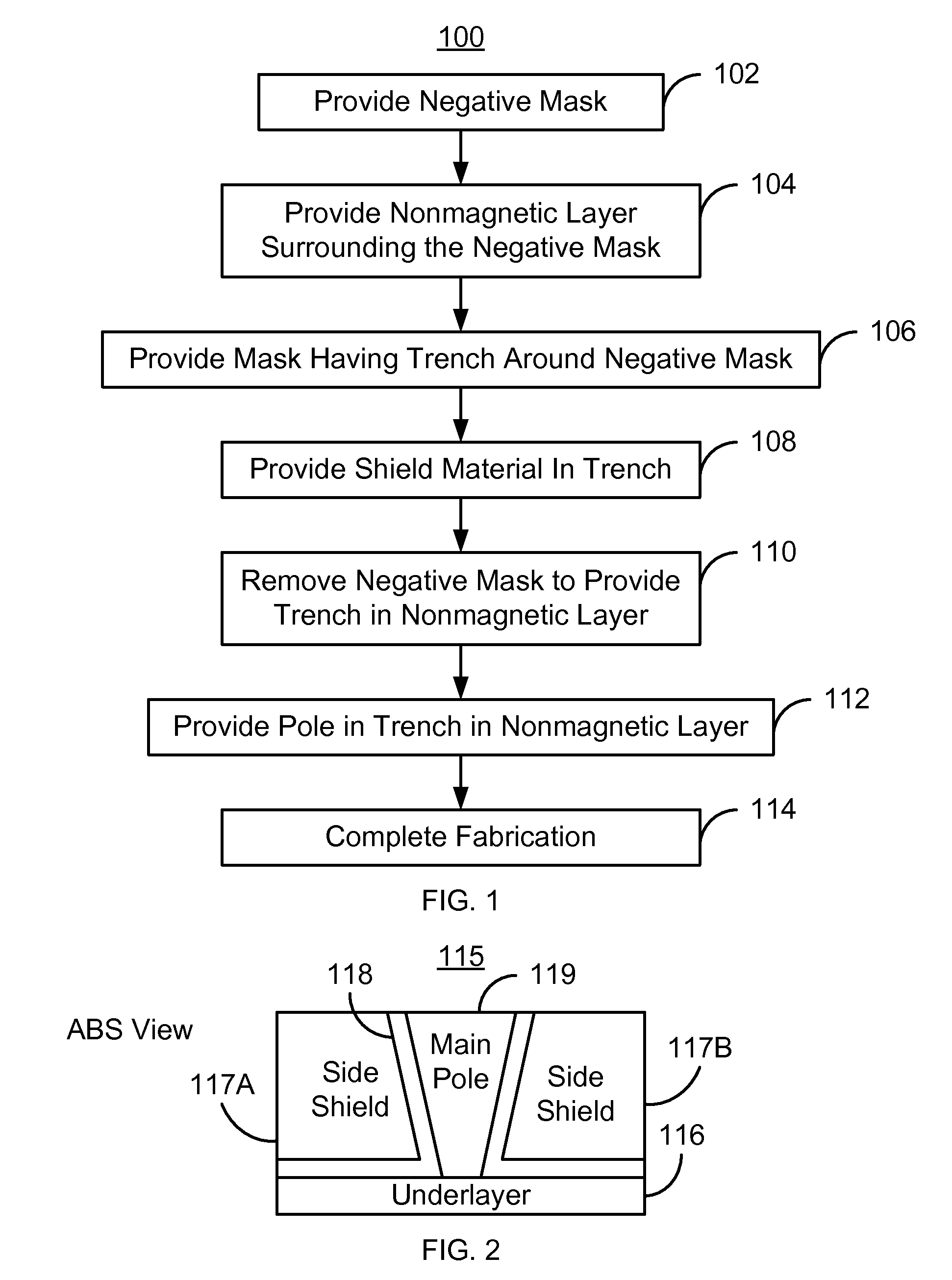
[0022]FIG. 1 is a flow chart depicting an exemplary embodiment of a method 100 for fabricating a magnetic recording transducer having side shields. For simplicity, some steps may be omitted or combined. The method 100 is also described in the context of providing a single recording transducer. However, the method 100 may be used to fabricate multiple transducers at substantially the same time. The method 100 is also described in the context of particular layers. A particular layer may include multiple materials and / or multiple sublayers. The method 100 also may start after formation of other portions of the magnetic recording transducer. For example, the method 100 commences after formation of an underlayer. The underlayer is nonmagnetic may be an insulator, such as aluminum oxide. Further, a leading shield may have been formed below the underlayer.

[0023]A negative mask is provided, via step 102. The negative mask has a profile that corresponds to the desired profile of the final po...


PUM

PropertyMeasurementUnit
Widthaaaaaaaaaa
Non-magneticaaaaaaaaaa

Abstract

A method for manufacturing a magnetic transducer is described. The method includes providing a negative mask having a bottom, a plurality of sides, and a top wider than the bottom. The method also includes depositing a nonmagnetic layer on the negative mask. The nonmagnetic layer has a plurality of portions covering the plurality of sides of the negative mask. The method also includes providing a first mask having a first trench therein. The negative mask resides in the first trench. The method further includes depositing side shield material(s), at least a portion of which resides in the first trench. The method further includes removing the negative mask to create a second trench between the plurality of portions of the nonmagnetic layer and form a pole, at least a portion of which resides in the second trench.

Description

CROSS REFERENCE TO RELATED APPLICATIONS[0001]This application is a divisional of U.S. patent application Ser. No. 12 / 239,321, filed on Sep. 26, 2008, now pending, which is hereby incorporated by reference in its entirety.BACKGROUND[0002]Side shields, as well as top shields, may be desired in conventional magnetic recording transducers, particular perpendicular magnetic recording (PMR) transducers. Side shields in combination with top shields that surround the sides and top of the main PMR pole are termed wrap-around shields. Various conventional methods are available to fabricate wrap-around shields. For example, some conventional methods deposit a magnetic layer and trim the layer to form a conventional PMR pole. Once the conventional PMR pole is formed, nonmagnetic layer(s), as well as shields, are provided around the conventional pole. Although this method functions at lower recording densities, at higher recording densities issues arise. Higher recording densities correspond to ...

Claims


Application Information

Patent Timeline
IPC IPC(8): G11B5/11G11B5/127G11B5/31H04R31/00
CPCG11B5/315G11B5/3163G11B5/33G08B13/246Y10T29/49043Y10T29/49044Y10T29/49039Y10T29/49048Y10T29/49052Y10T29/49041
Inventor TRAN, UTBAI, ZHIGANGLIN, KEVIN K.HE, LI
Owner WESTERN DIGITAL TECH INC
Why Eureka
Try Eureka