Method and system for providing a hard bias structure in a magnetic recording transducer

a technology of hard bias and magnetic recording transducer, which is applied in the field of providing a hard bias structure in a magnetic recording transducer, can solve the problems of destabilizing the free layer and affecting the performance of the conventional magnetic transducer

Inactive Publication Date: 2013-10-01
WESTERN DIGITAL TECH INC
View PDF26 Cites 148 Cited by
  • Summary
  • Abstract
  • Description
  • Claims
  • Application Information

AI Technical Summary

Benefits of technology

[0007]FIG. 1 is a diagram of a portion of a conventional transducer including conventional hard bias structure.

Problems solved by technology

As a result, the free layer may be destabilized.
Consequently, performance of the conventional magnetic transducer may be adversely affected

Method used


Image

  • Method and system for providing a hard bias structure in a magnetic recording transducer
  • Method and system for providing a hard bias structure in a magnetic recording transducer
  • Method and system for providing a hard bias structure in a magnetic recording transducer

Examples


Embodiment Construction

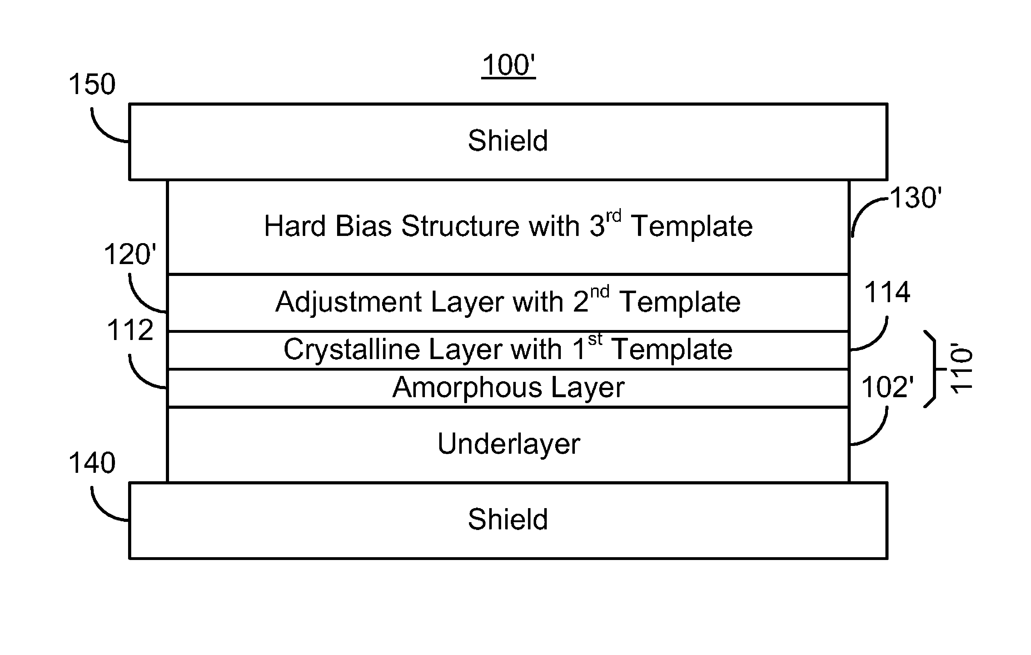
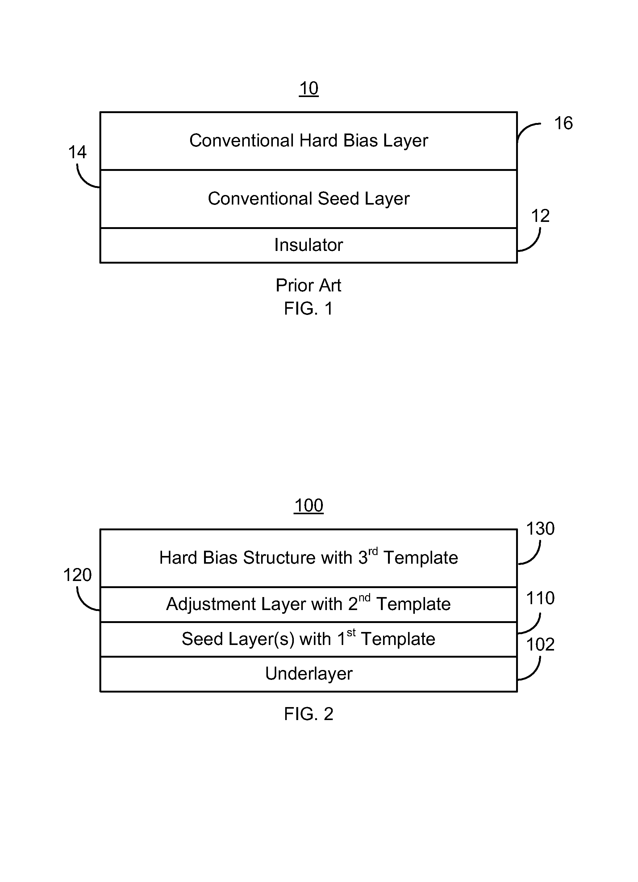
[0016]FIG. 2 depicts a magnetic transducer 100 including an exemplary embodiment of a hard bias structure. The magnetic transducer 100 may be a read transducer that might be part of a merged head that also includes a write transducer (not shown) and resides on a slider (not shown) of a disk drive (not shown). The transducer 100 is also described in the context of particular layers. However, in some embodiments, such layers may include sub-layer(s). Further, although certain layer(s) are described in the context of a single template, a layer may have multiple templates not inconsistent with the description herein. For clarity, FIG. 2 is not drawn to scale.

[0017]The magnetic transducer 100 includes an underlayer 102, one or more seed layers 110, at least one adjustment layer 120, and a hard bias structure 130. The seed layer(s) 110 includes one or more layers. In some embodiments, the seed layer(s) 110 may include an amorphous layer and a crystalline layer on the amorphous layer. For ...


PUM

PropertyMeasurementUnit
thicknessesaaaaaaaaaa
thicknessaaaaaaaaaa

Abstract

A method and system for providing a magnetic transducer is described. The method and system include providing a seed layer and providing at least one adjustment layer on the seed layer. The method and system also include providing a hard bias structure on the at least one adjustment layer. The seed layer has a first template including a first template dimension and a first texture. The at least one adjustment layer has a second template including a second template dimension and a second texture. The hard bias structure has a third template including a third template dimension and a third texture. The second template is between the first template and the third template.

Description

BACKGROUND[0001]FIG. 1 depicts a portion of a conventional magnetic transducer 10, such as a conventional read transducer or other device. The conventional transducer 10 includes a conventional hard bias layer 16 and a conventional seed layer 14 that may reside on a conventional insulator 12. The conventional read transducer 10 would typically include also a conventional bottom shield, a read sensor, conventional leads, conventional insulator, and a conventional top shield, which are not shown for clarity.[0002]The conventional seed layer 14 is formed prior to the conventional hard bias layer 16. The seed layer 14 is desired to provide a surface suitable for growth of the conventional hard bias layer 16. The conventional seed layer 14 is typically composed of a layer of Cr, CrV, or CrTi. Alternatively, the conventional seed layer 14 may be a bilayer including a Ta underlayer (not separately shown) and a W layer (not separately shown) between the conventional hard bias layer 16 and t...

Claims


Application Information

Patent Timeline
Patent Type & Authority Patents(United States)
IPC IPC(8): G11B5/127
CPCG11B5/3932Y10T428/1171
Inventor ROY, ANUP GHOSHMAO, MINGPAKALA, MAHENDRA
Owner WESTERN DIGITAL TECH INC
Why Eureka
Try Eureka