Method for providing a magnetic recording transducer

a technology of magnetic recording and transducer, which is applied in the manufacture of head surfaces, magnetic bodies, furnaces, etc., can solve the problems of insufficient ra and tmr of crystalline tunneling barriers fabricated using the conventional method, adversely affecting the performance of conventional magnetic elements, and insufficient improvement of ra and tmr

Inactive Publication Date: 2013-02-26
WESTERN DIGITAL TECH INC
View PDF25 Cites 148 Cited by
  • Summary
  • Abstract
  • Description
  • Claims
  • Application Information

AI Technical Summary

Problems solved by technology

Although the method 10 may be used to fabricate a tunneling magnetoresistive element, there may be drawbacks.
However, the conventional crystalline tunneling barrier fabricated using the conventional method 10 may produce insufficient RA and TMR for high density recording applications.
However, the improvement in RA and TMR may be insufficient.
Further, heating performed in step 18 may not significantly improve the conventional MgO barrier layer and may cause diffusion of portions of the pinning layer and SAF, which adversely impacts performance of the conventional magnetic element.

Method used


Image

  • Method for providing a magnetic recording transducer
  • Method for providing a magnetic recording transducer
  • Method for providing a magnetic recording transducer

Examples


Embodiment Construction

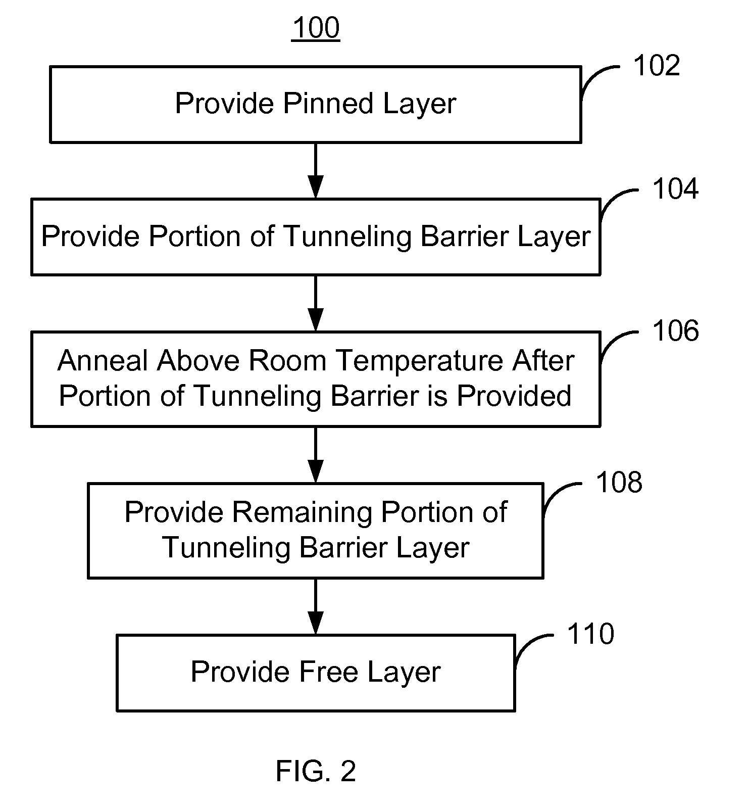
[0012]FIG. 2 is a flow chart of an exemplary embodiment of a method 100 for fabricating a magnetoresistive element, particularly a tunneling magnetoresistive element for use as a read sensor in a read transducer. For simplicity, some steps may be omitted or combined with other steps. The method 100 also may commence after formation of other structures of the read transducer, such as shields. The method 100 is also described in the context of providing a single magnetoresistive structure. However, the method 100 may be used to fabricate multiple structures at substantially the same time. The method 100 is also described in the context of particular layers. However, in some embodiments, such layers may include sub-layer(s).

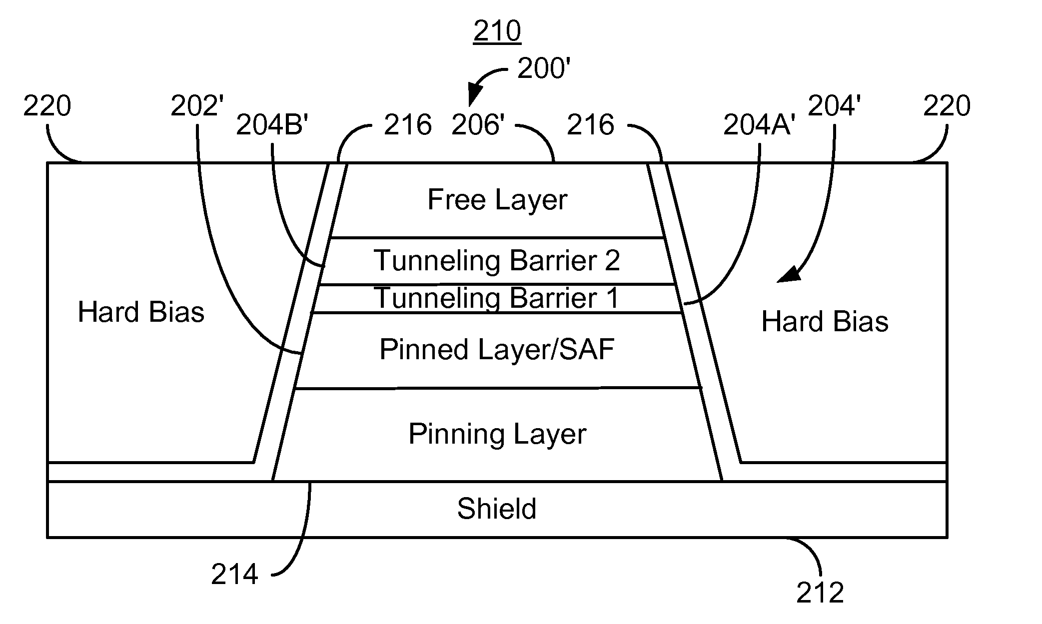
[0013]A pinned layer of the magnetic element is provided, via step 102. In one embodiment, the pinned layer is provided on a pinning layer or other layer configured to fix, or pin, the magnetization of the pinned layer in a particular direction. The direction may in...


PUM

PropertyMeasurementUnit
temperatureaaaaaaaaaa

Abstract

A method for providing a magnetic recording transducer is described. The method includes providing a pinned layer for a magnetic element. In one aspect, a portion of a tunneling barrier layer for the magnetic element is provided. The magnetic recording transducer annealed is after the portion of the tunneling barrier layer is provided. The annealing is at a temperature higher than room temperature. A remaining portion of the tunneling barrier layer is provided after the annealing. In another aspect, the magnetic transducer is transferred to a high vacuum annealing apparatus before annealing the magnetic transducer. In this aspect, the magnetic transducer may be annealed before any portion of the tunneling barrier is provided or after at least a portion of the tunneling barrier is provided. The annealing is performed in the high vacuum annealing apparatus. A free layer for the magnetic element is also provided.

Description

BACKGROUND[0001]FIG. 1 depicts a conventional method 10 for forming a tunneling magnetoresistive element in a read transducer. The read transducer includes a magnetic tunneling junction formed using the method 10. The layers in the magnetoresistive sensor, or stack, below the conventional tunneling barrier layer are deposited, via step 12. The magnetoresistive stack is typically formed on other structures, such as, shield(s), and / or write transducer(s). The magnetoresistive stack layers are typically blanket deposited. The layers below the tunneling barrier layer typically include seed layer(s), a conventional antiferromagnetic (AFM) layer, and a conventional pinned layer. A metallic Mg layer may optionally be deposited, via step 14. The Mg layer may be desired for the conventional MgO barrier layer. A conventional MgO barrier layer is deposited, via step 16. The conventional MgO barrier layer is a crystalline insulator. After deposition of the conventional MgO barrier layer, the tr...

Claims


Application Information

Patent Timeline
Patent Type & Authority Patents(United States)
IPC IPC(8): G11B5/127H04R31/00
CPCB82Y10/00B82Y40/00G01R33/098G11B5/3163G11B5/3906G11B5/3909H01F10/3254H01F10/3268H01F41/303H01F41/307H01L43/08H01L43/12B82Y25/00Y10T29/49044Y10T29/49046Y10T29/49052Y10T29/49043Y10T29/49039Y10T29/49048Y10T29/49041H10N50/10H10N50/01F27D7/06F27D19/00G11B5/127G11B5/3109
Inventor PARK, CHANDOLENG, QUNWENPAKALA, MAHENDRA
Owner WESTERN DIGITAL TECH INC
Why Eureka
Try Eureka