Method and system for providing a read transducer having an extended pinned layer and soft magnetic bias structures with improved stability

a technology of soft magnetic bias and read transducer, which is applied in the field of providing a read transducer having an extended pinned layer and soft magnetic bias structure with improved stability, can solve problems such as adversely affecting the reliability of conventional read transducers

Active Publication Date: 2014-06-24
WESTERN DIGITAL TECH INC
View PDF116 Cites 139 Cited by
  • Summary
  • Abstract
  • Description
  • Claims
  • Application Information

AI Technical Summary

Problems solved by technology

Such instabilities adversely affect reliability of the conventional read transducer 50.

Method used


Image

  • Method and system for providing a read transducer having an extended pinned layer and soft magnetic bias structures with improved stability
  • Method and system for providing a read transducer having an extended pinned layer and soft magnetic bias structures with improved stability
  • Method and system for providing a read transducer having an extended pinned layer and soft magnetic bias structures with improved stability

Examples


Embodiment Construction

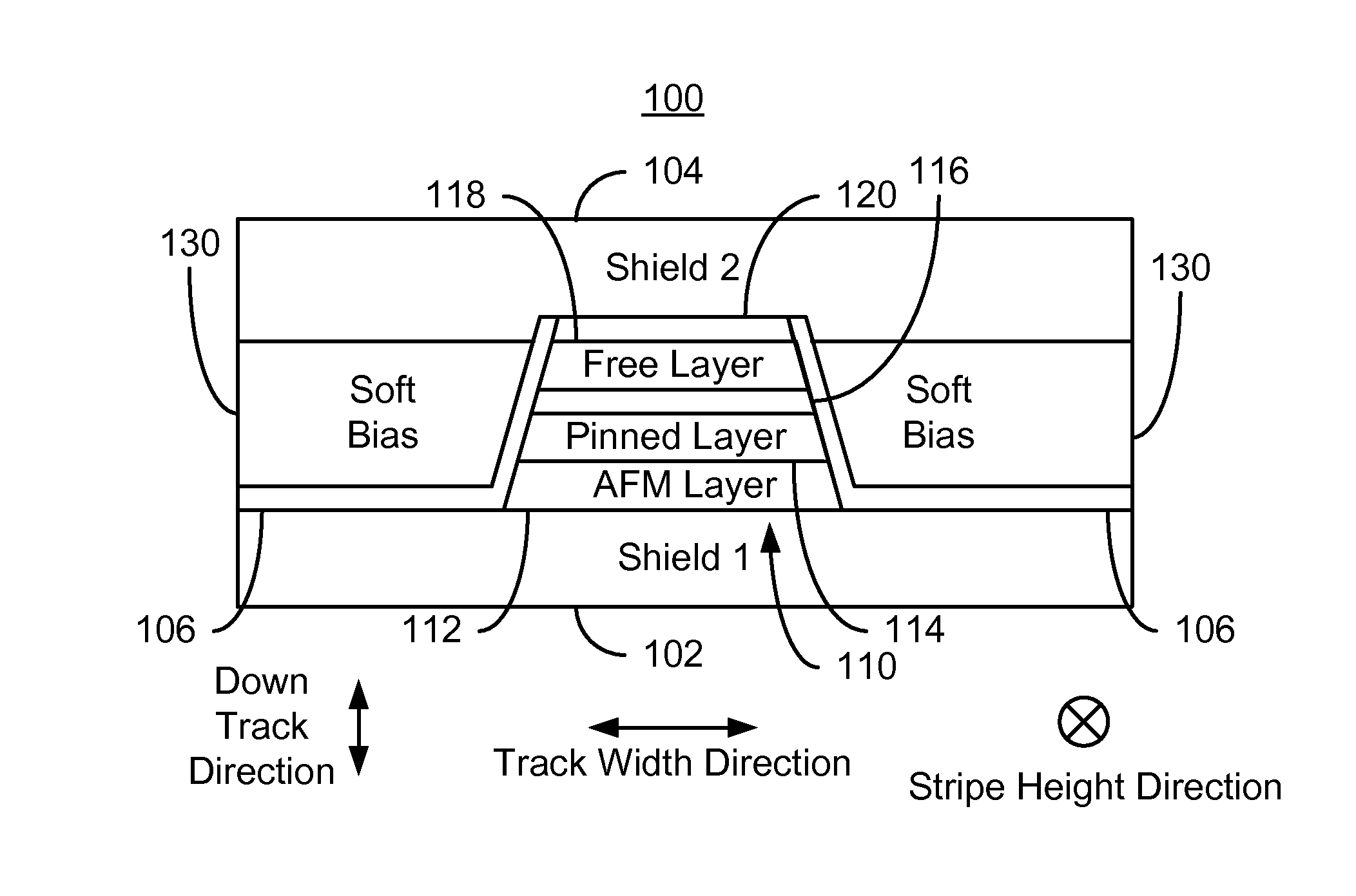
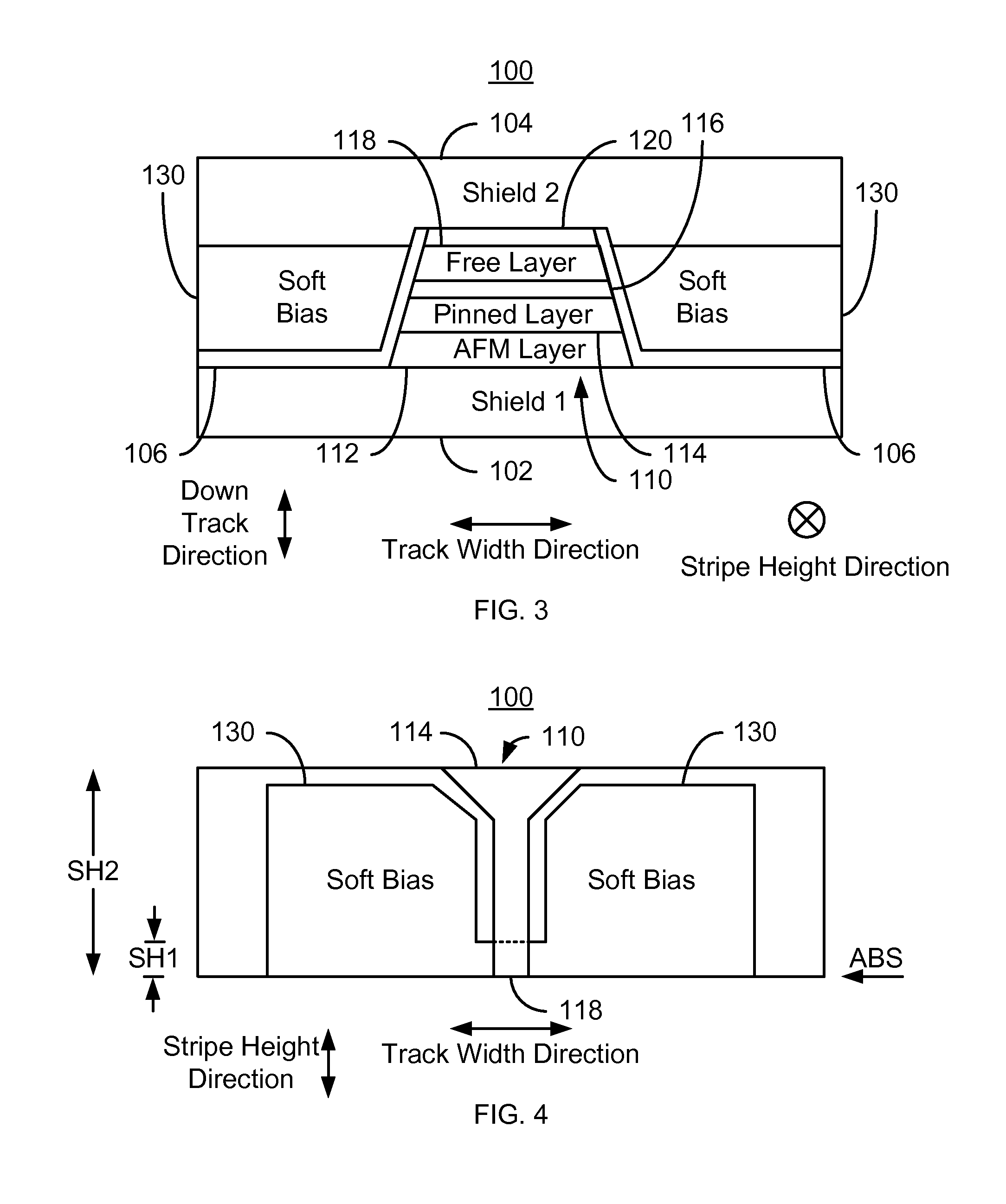
[0020]FIGS. 3-4 depict ABS and plan views, respectively, of an exemplary embodiment of a portion of a magnetic read transducer 100. For clarity, FIGS. 3 and 4 are not to scale. The read transducer 100 may be part of a read head or may be part of a merged head that also includes a write transducer. The head of which the read transducer 100 is a part is part of a disk drive having a media, a slider and the head coupled with the slider. The read transducer 100 is also described in the context of particular components. In other embodiments, some of the components may be omitted, provided in a different location, or have different constituents. Further, other components may be used.

[0021]The transducer 100 includes shields 102 and 104, insulator 106, a read sensor 110 and soft magnetic bias structures 130. For clarity, the insulator 106 is not shown in the plan view. The sensor 110 shown is a GMR or TMR sensor. Thus, the sensor 110 includes a pinning layer 112, a pinned layer 114, a nonm...


PUM

PropertyMeasurementUnit
heightaaaaaaaaaa
coercivityaaaaaaaaaa

Abstract

A method and system provide a magnetic transducer having an air-bearing surface (ABS). The magnetic transducer includes a first shield, a read sensor, at least one soft magnetic bias structure and a second shield. The read sensor includes a sensor layer, a pinned layer and edge(s). The sensor layer has a first stripe height in a stripe height direction perpendicular to the ABS. The pinned layer has a second stripe height in the stripe height direction. The second stripe height is greater than the first stripe height. The soft magnetic bias structure(s) are adjacent to the edge(s) of the sensor. A portion of the soft magnetic bias structure(s) is further from the ABS than the first stripe height. The read sensor is between the first shield and the second shield. The soft magnetic bias structure(s) extend to the second shield.

Description

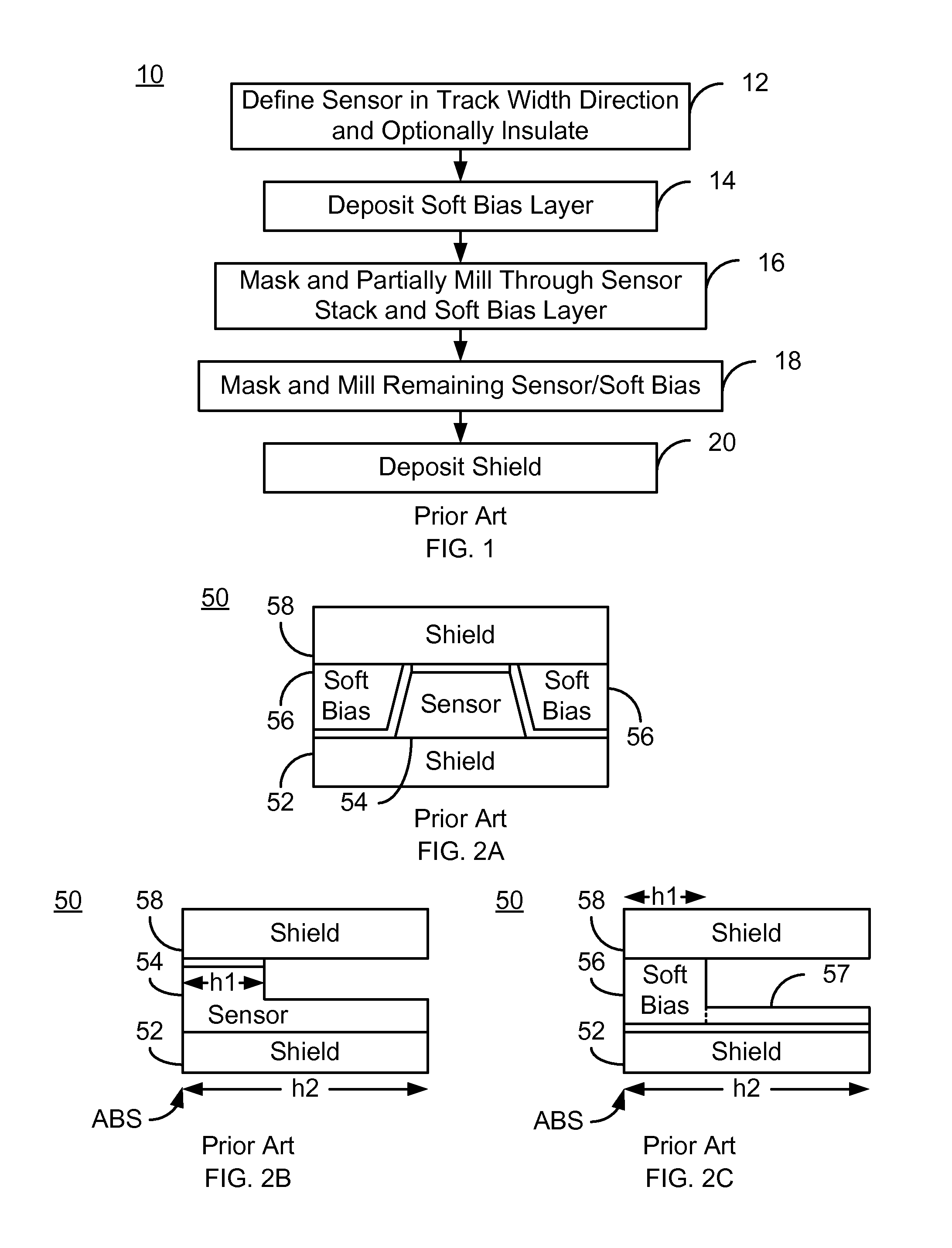
BACKGROUND[0001]FIG. 1 depicts a conventional method 10 for fabricating a read transducer that uses soft magnetic biasing. The method 10 starts after the first shield has been provided and the layers for the sensor are deposited. The sensor is defined in the track width direction, via step 12. Step 12 typically includes providing a first mask that covers the desired portion of the sensor layers in the track width direction and milling the exposed portions of the sensor layers. In addition, an insulating layer may be deposited. The soft bias layer is deposited, via step 14. The insulating layer electrically insulates the sensor from the soft bias material(s). The first mask may then be removed.[0002]The read sensor is then masked and partially milled through, via step 16. The first conventional milling mask used in step 16 sets the stripe height of the free layer. The stripe height of the free layer is the distance the free layer extends from the ABS in a direction perpendicular to t...

Claims


Application Information

Patent Timeline
Patent Type & Authority Patents(United States)
IPC IPC(8): G11B5/127
CPCG11B5/127G11B5/3163G11B5/3932G11B5/398G11B5/3912H01L43/02H01L43/12H01L43/08H10N50/80H10N50/01
Inventor LI, GUANXIONGMAO, MINGHU, CHIH-CHING
Owner WESTERN DIGITAL TECH INC
Why Eureka
Try Eureka