Magnetic recording head with dynamic fly height heating and having thermally controlled pole tip protrusion to control and protect reader element

a recording head and dynamic technology, applied in the field of magnetic recording heads with dynamic fly height, can solve problems such as damage to read sensors and inability to ensur

Active Publication Date: 2014-06-10
WESTERN DIGITAL TECH INC
View PDF71 Cites 140 Cited by
  • Summary
  • Abstract
  • Description
  • Claims
  • Application Information

AI Technical Summary

Problems solved by technology

Thermal actuators cause touchdown and sensors detect touchdown; however, this does not ensure that the point where touchdown is made is actually sensed at the same location, or sensed at

Method used


Image

  • Magnetic recording head with dynamic fly height heating and having thermally controlled pole tip protrusion to control and protect reader element
  • Magnetic recording head with dynamic fly height heating and having thermally controlled pole tip protrusion to control and protect reader element
  • Magnetic recording head with dynamic fly height heating and having thermally controlled pole tip protrusion to control and protect reader element

Examples


Embodiment Construction

[0007]In the following detailed description, numerous specific details are set forth to provide a full understanding of the present invention. It will be apparent, however, to one ordinarily skilled in the art that the present invention may be practiced without some of these specific details. In other instances, well-known structures and techniques have not been shown in detail to avoid unnecessarily obscuring the present invention.

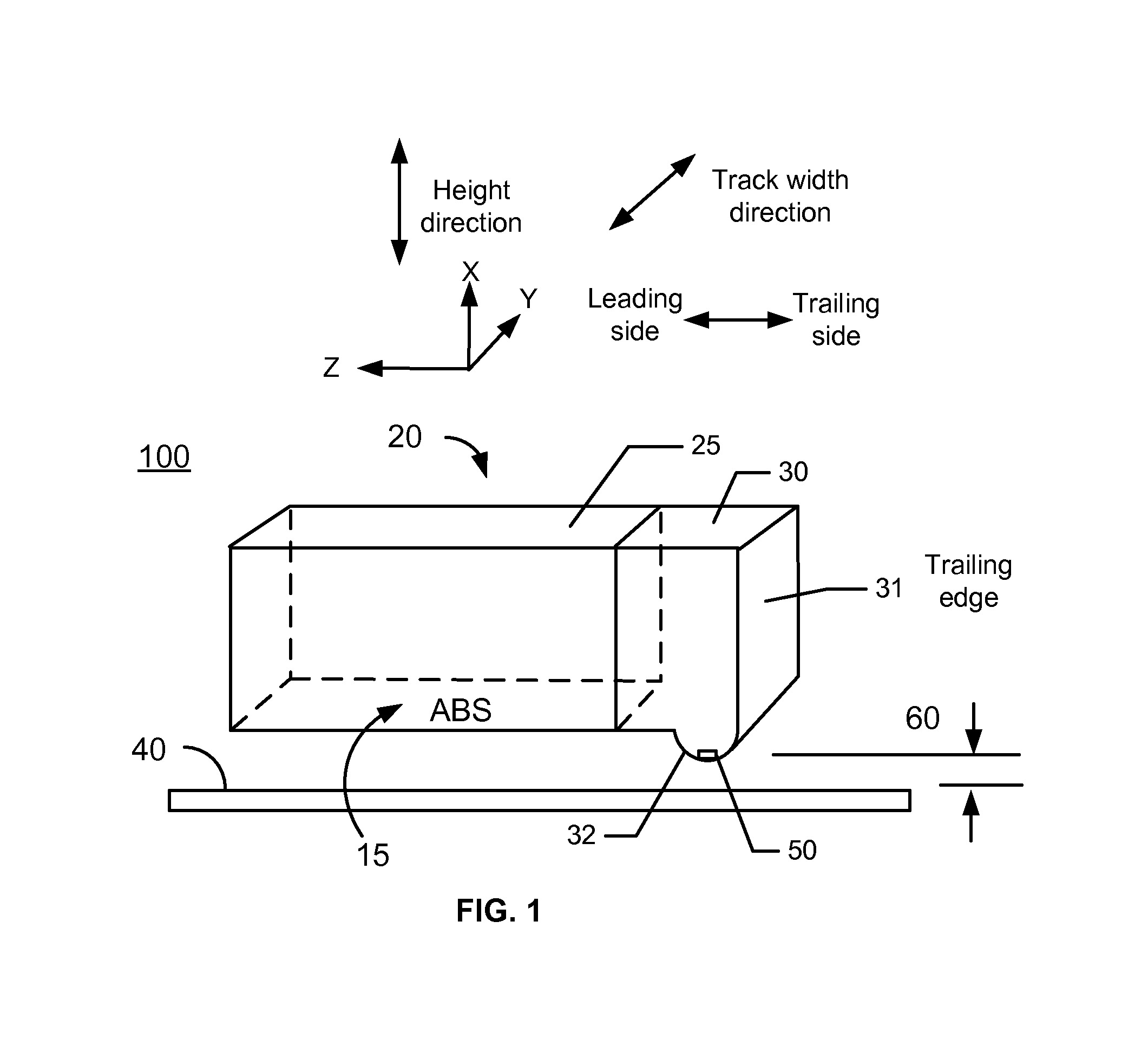
[0008]FIG. 1 illustrates a hard disk drive (HDD) 100 that includes a slider 20 and recording media 40. Slider 20 includes body 25 and a magnetic recording head 30 on the trailing side of body 25. Body 25 may be much larger than magnetic recording head 30, and figures are highly simplified for clarity. Slider 20 has a bottom surface 15, hereinafter called an air bearing surface (ABS), which faces recording media 40. During operation, recording media 40 rotates under slider 20, and due to aerodynamic forces generated between ABS 15 and recording media 40, f...


PUM


Abstract

A magnetic recording device includes a slider having an air bearing surface (ABS), a leading side, and a trailing side and a head residing on the slider. The head has a first magnetic transducer and a first heater for heating an area proximal to the first magnetic transducer. A first shield (S1) comprising a first material is on the leading side of the first magnetic transducer and a second shield (S2) comprising the first material is on the trailing side of the first magnetic transducer. A first pole (P1) comprising the first material is on the trailing side of the second shield (S2), and the first pole (P1) is between 0.6 micron and 2.0 micron thick; and the second shield (S2) is less than 0.6 micron thick. A hard disk drive includes the magnetic recording device.

Description

BACKGROUND OF THE INVENTION[0001]Disk drives typically use heads residing on sliders to read from and write to the magnetic media. Read and write transducers residing in the head are flown at a small, controlled spacing above the magnetic medium during read and write operations. An air bearing forms between the head and the disk due to the disk rotating at high speeds. It may be desirable to estimate a fly height of the head, for example, when a system controls the fly height in order to optimize the write / read signals. To determine the controlled spacing, it may be desirable for the disk drive to detect at what point the head contacts the media, known as a touchdown event. Touchdown sensing may be accomplished by detecting actual contact or by proximity sensing methods. In addition, touchdown may be determined without dedicated sensors, for example using readback signal from the read transducer, position error signal (PES) from the servo, or other means.[0002]For example, heads may...

Claims


Application Information

Patent Timeline
IPC IPC(8): G11B5/127
CPCG11B5/127G11B5/607G11B5/1278G11B5/6076
Inventor KNUTSON, NEILFOWLER, DAVID E.LO, YU
Owner WESTERN DIGITAL TECH INC
Why Eureka
Try Eureka