
Mobile communication system, and mobile unit, base station unit and method therefore

a mobile communication system and mobile technology, applied in the field of mobile communication system, can solve the problems of affecting spectral efficiency and time efficiency, and the mobile unit under control by the base station unit of the eutra/eutran mobile communication system may not always be able to set, so as to achieve the effect of utilizing the radio frequency spectrum more efficiently

Active Publication Date: 2013-02-12
SHARP KK
View PDF11 Cites 2 Cited by
  • Summary
  • Abstract
  • Description
  • Claims
  • Application Information

AI Technical Summary

Benefits of technology

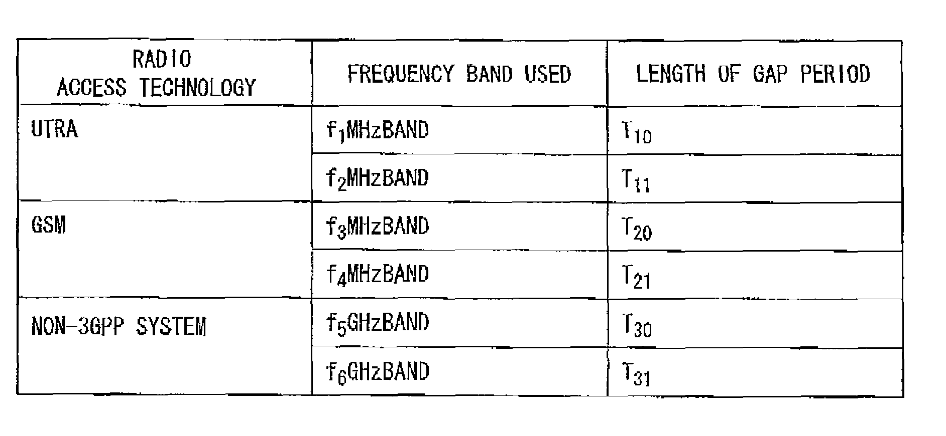
The patent allows a base station to monitor different types of radio access technology by setting a gap period. This helps to avoid wasting spectrum and improves efficiency.

Problems solved by technology

As a result, a mobile unit under control by a base station unit of the EUTRA / EUTRAN mobile communication system may not always be able to set, in the inter-RAO-HO (and the inter-freq-HO), the length of the gap period which is optimum to such radio access technology, due to the difference in minimum required gap length for the monitoring or measurement of a different radio access technology-based base station unit.
When the length of the gap period is set at a value longer than a minimum required gap, that results in an unutilized portion in the gap period, adversely affecting the spectral efficiency as well as the time efficiency.

Method used


Image

  • Mobile communication system, and mobile unit, base station unit and method therefore
  • Mobile communication system, and mobile unit, base station unit and method therefore
  • Mobile communication system, and mobile unit, base station unit and method therefore

Examples


first embodiment

[0067]A mobile communication system according to a first embodiment of the invention will now be described.

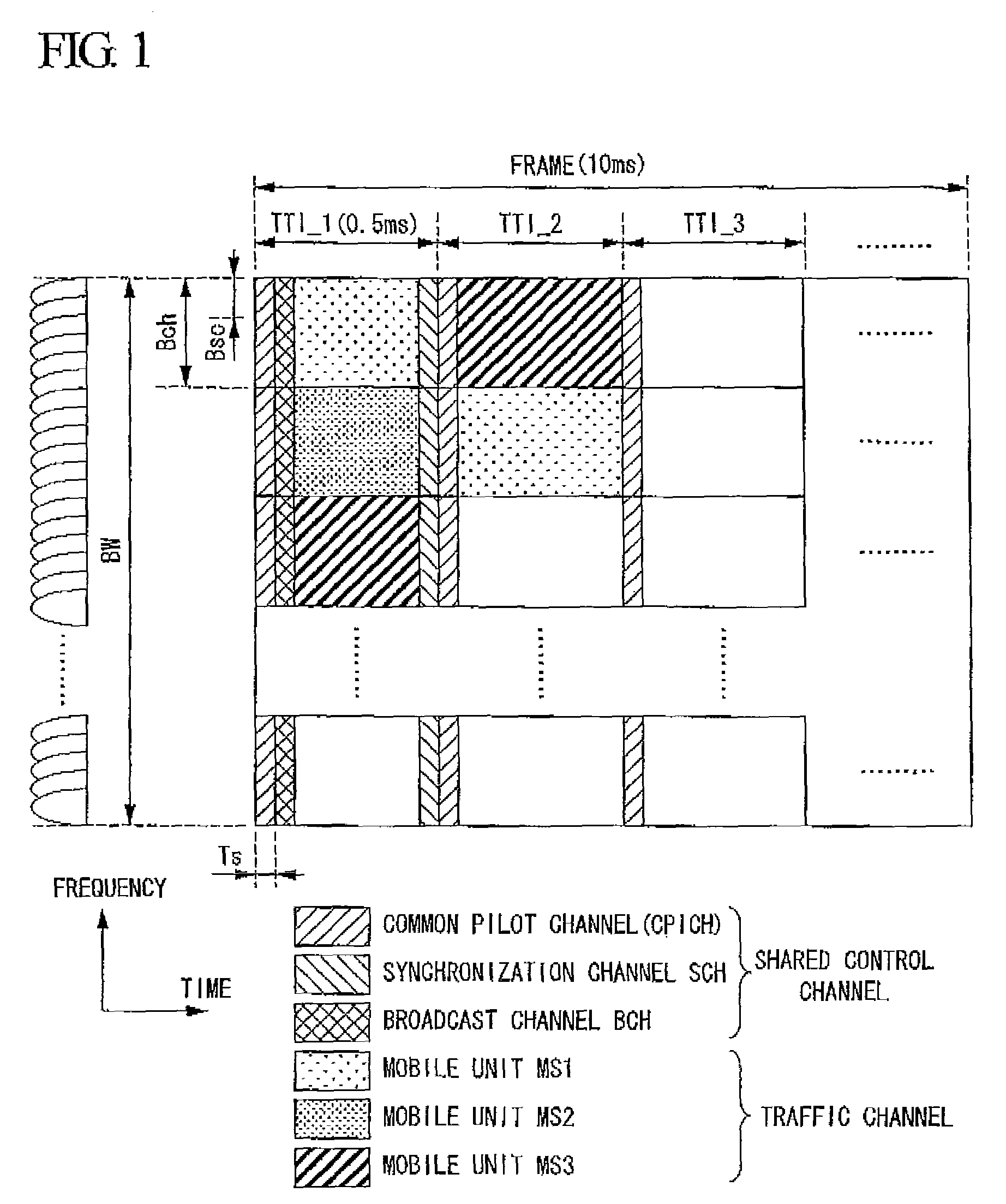
[0068]In FIG. 1 showing an example of the downlink radio signal frame structure for the 3GPP-based EUTRA with time and frequency taken along the abscissa and the ordinate, respectively, the downlink radio frame consists of a plurality of subcarriers occupying two dimensional radio resource blocks RB defined by frequency bandwidth Bch and transmission timing interval TTI. In FIG. 1, BW denotes the frequency bandwidth of the downlink signal; Bch, frequency bandwidth of the resource block; Bsc, frequency bandwidth of the subcarrier; and Ts, an OFDM symbol length.

[0069]As shown in FIG. 1, common pilot channel CPICH is mapped to the leading portion of each of the TTL while broadcast channel BCH and synchronization channel SCH are mapped to the leading portion of each frame of the radio signal A part of the rest of each resource block is used as a traffic channel TCH, while it is map...

second embodiment

[0136]The second embodiment of the present invention is a mobile communication system in which a mobile unit is capable of performing the inter-RAT-HO (and inter-freq-HO) to a plurality of mutually different mobile communication systems, and in which the base station unit simultaneously sets a plurality of uplink resource allocation intervals or downlink resource allocation intervals for the instantaneous CQI value feedback without being informed by the mobile unit about the type of radio access technology to be monitored and measured by the mobile unit. The makeup of base station unit according to the second embodiment is similar to that of the first embodiment (FIGS. 6 and 7 referred to), with only the processing being different.

[0137]Referring to FIG. 10 showing an illustration for describing the resource allocation interval in the base station unit of the second embodiment, the base station unit determines that the instantaneous CQI value fed back from the mobile unit is smaller...


PUM


Abstract

In mobile communication system having a plurality of mobile traits and a plurality of base station units, the system of the present invention is characterized in that the base station unit has a gap period length setting section for setting the length of the gap period for the mobile unit depending on the type of the radio access technology to be monitored by the mobile unit.

Description

TECHNICAL FIELD[0001]The present invention relates to a mobile communication system, and a mobile unit, a base station unit and a mobile communication method therefore and, particularly to such system, and a mobile unit, a base station unit, and a mobile communication method adapted to provide wireless communication between cells to which the same frequencies are assigned under the same radio access technology, between cells to which mutually different frequencies are assigned under the same radio access technology, or between cells under mutually different radio access technologies.[0002]Priority is claimed on Japanese Patent Application No. 2006-136259 filed May 16, 2006, the content of which is incorporated herein by reference.BACKGROUND ART[0003]In a cellular mobile communication system based on the same radio access technology (RAT), a number of base station units are remotely located, each of which constitutes a wireless communication area, thereby to provide a service area, w...

Claims


Application Information

Patent Timeline
Patent Type & Authority Patents(United States)
IPC IPC(8): H04B7/00H04W24/10H04W36/14
CPCH04W36/0088H04W24/10H04W36/14H04W36/142
Inventor NAKASHIMA, DAIICHIROTSUBOI, HIDEKAZU
Owner SHARP KK
Learn More