Insulated poured concrete wall structure with integal T-beam supports and method of making same

a technology of poured concrete and tbeam supports, which is applied in the field of building wall structures, can solve the problems of increasing costs, poor insulators, and increasing methods, and achieves the effects of less concrete, less concrete, and less cos

Inactive Publication Date: 2013-02-19
WEILER NEAL RAY
View PDF29 Cites 18 Cited by
  • Summary
  • Abstract
  • Description
  • Claims
  • Application Information

AI Technical Summary

Benefits of technology

[0014]The present invention provides an insulated concrete wall structure designed to satisfy the aforementioned need. The wall structure of the present invention is a concrete wall poured onsite in thereby eliminating the need for large cranes and the like at the construction site as required when using prefabricated wall panels. Further, the wall structure of the present invention incorporates the use of concrete T-beam supports which are formed onsite through the use of spaced insulations panels that not only provides an insulated wall structure with a high R value factor, but in addition thereto, the use of the integral concrete T-beam supports require less concrete and thus less costly as compared to standard poured walls having the same load bearing capacity. In the preferred embodiment, the insulated wall structure is formed on a concrete footer and the upright T-beam supports are formed on the footer and the upper ends of the upright T-beam supports are integrally connected together by a concrete box beam formed onsite along with the formation of the upright T-beam supports for unitary construction. Furthermore, upright rebars extend through each of the T-beam supports and are integrally connected to the lower footer and integrally connected to the upper box beam for interconnecting the T-beam supports, the footer and the box beam in a unified structure. And still further, the use of the insulation panels in the present invention not only provides for an insulated wall structure with a high R value, but also serve as the means for forming the unitary T-beam supports and the box beam, and also additionally provides the wall structure with an inner wall completely covered with insulation panels having a relatively smooth planar surface rather than an offset, stepped interrupted surface as is the case when using prefabricated panels.

Problems solved by technology

This method is both time consuming and labor intensive.
One drawback of all concrete walls however, is that they are poor insulators.
And generally speaking, the thicker the wall, the more concrete is needed and, more concrete usually equates to more and increased costs.
The above-described insulated, concrete poured walls inventions were basically directed to increasing the insulation “R” value of the poured wall, but none of them addressed the problem of the amount of concrete utilized in a given wall structure in an attempt to reduce the amount of concrete and thus the cost savings resulting therefrom.
Normally, this requires the use of a very large crane since the precast wall panels are extremely heavy.
One major disadvantage of using prefabricated panels is that for erection at the site, a large crane is required to lift and move the prefabricated panels into place and generally, these panels are set on a thin layer of compacted, crushed fine gravel which is in direct contrast to the long standing practice used for block and poured wall construction where a “concrete footing” (footer) is required for supporting the wall and the load supported by the wall.
Although the prefabricated panel wall construction meets the code requirements in many areas, it is questionable over the long run whether such compacted crush stone base is equivalent to the traditional footer construction, especially in the northern areas of the country where freezing and thawing must be taken into consideration in the construction of such walls.

Method used


Image

  • Insulated poured concrete wall structure with integal T-beam supports and method of making same
  • Insulated poured concrete wall structure with integal T-beam supports and method of making same
  • Insulated poured concrete wall structure with integal T-beam supports and method of making same

Examples


Embodiment Construction

[0054]In the following description, like reference characters designate like or corresponding parts throughout the several views of the drawings. Also in the following description, it is to be understood that such terms as “forward”, “rearward”, “left”, “right”, “upwardly”, “downwardly”, and the like are words of convenience and are not to be construed as limiting terms.

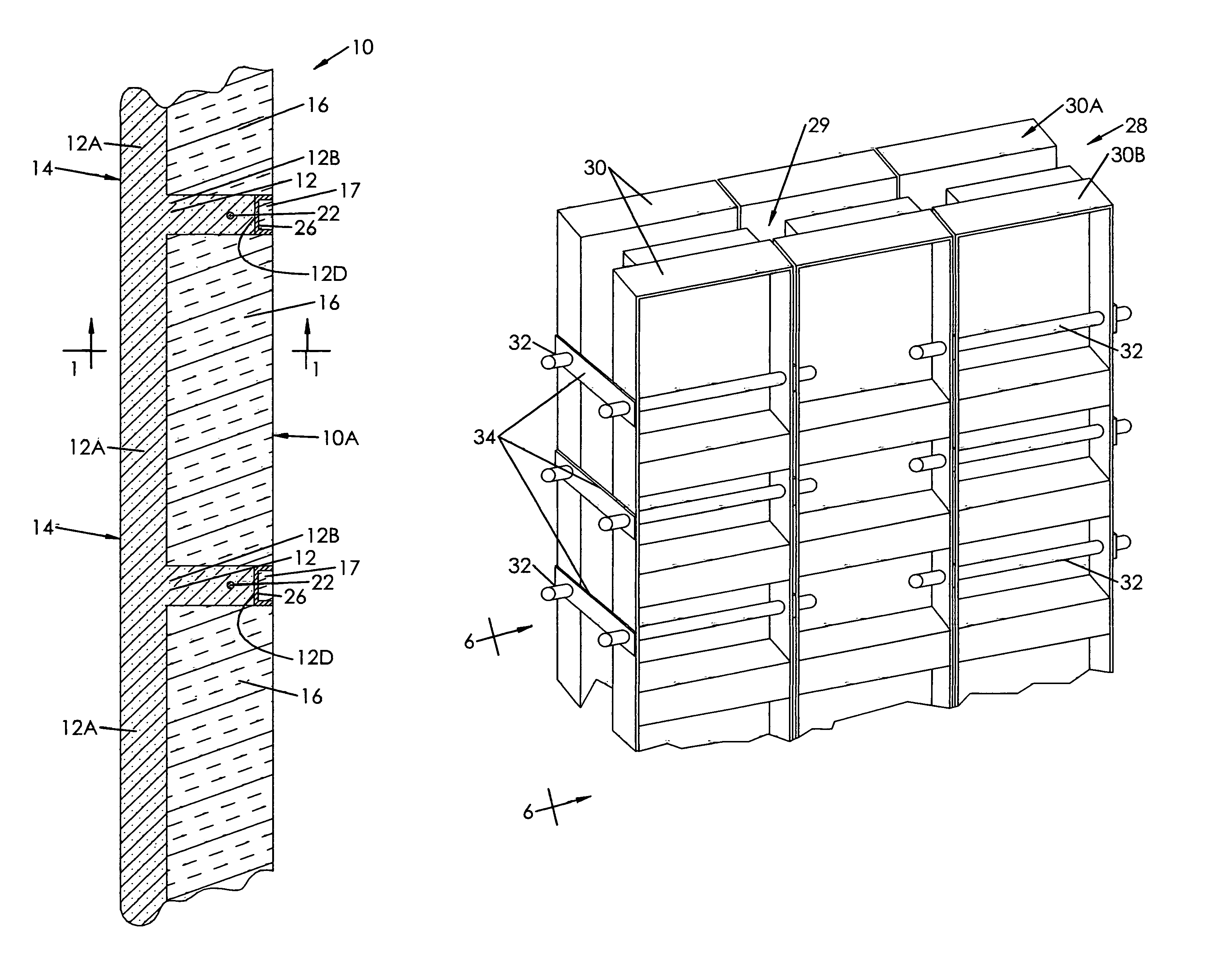
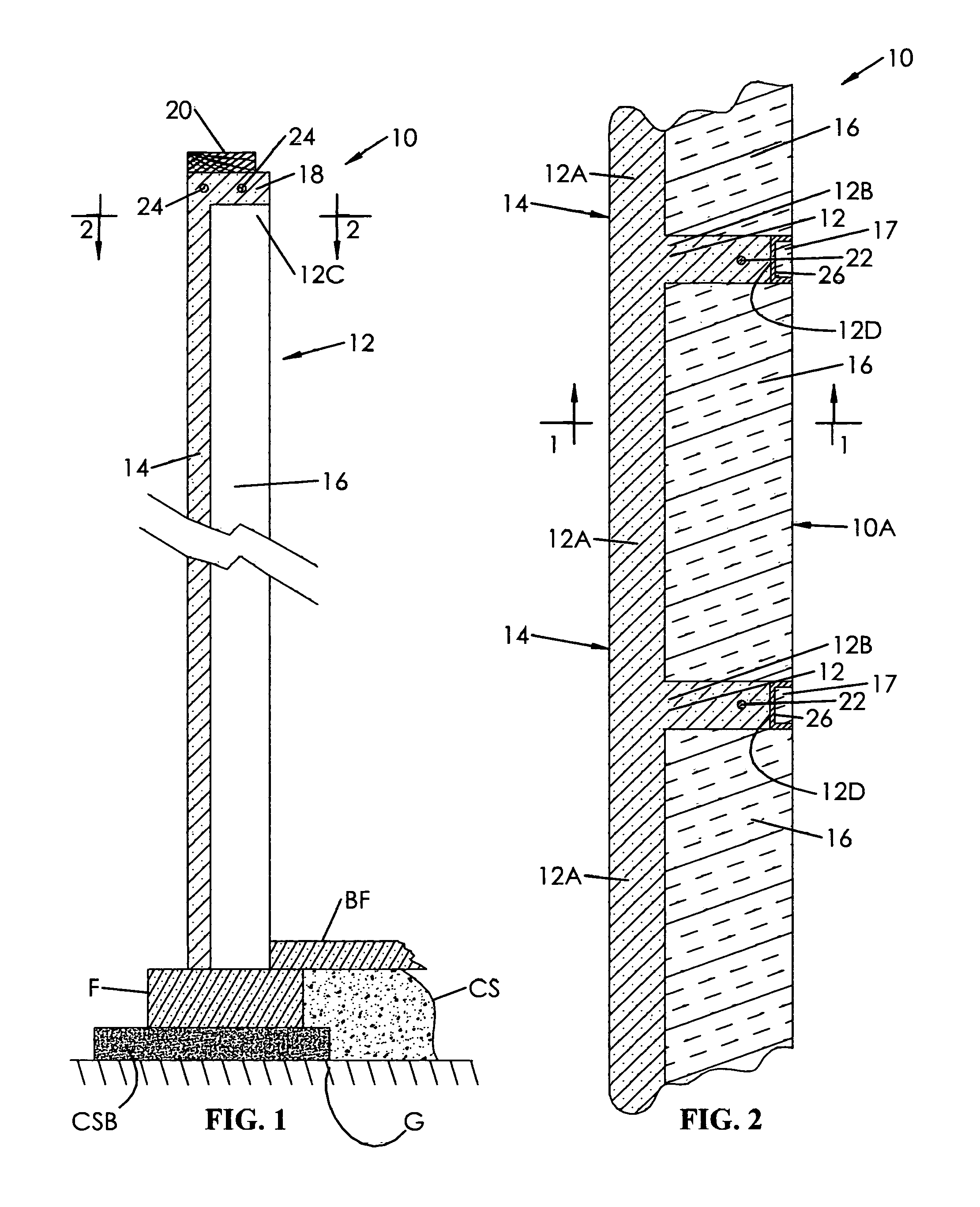
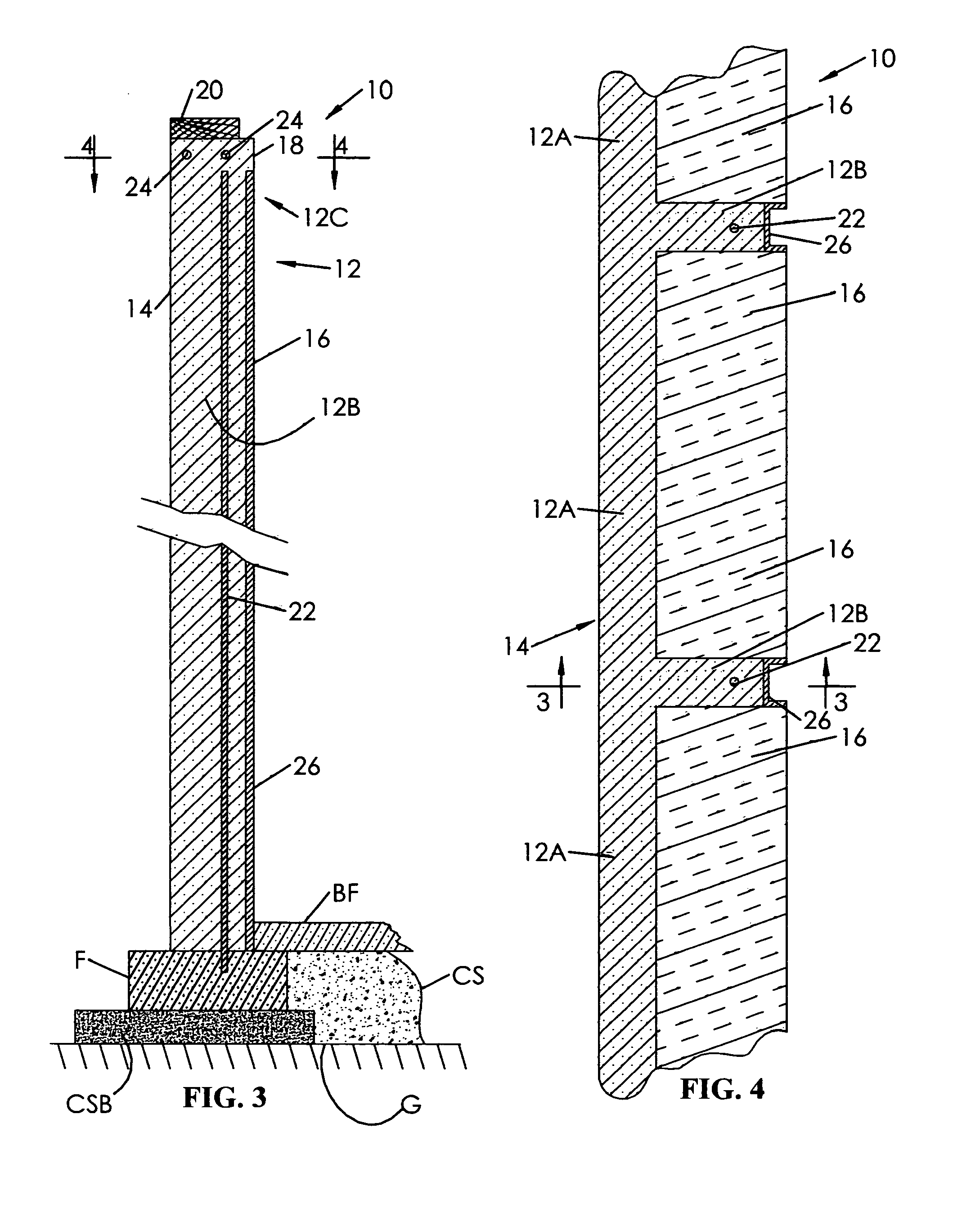
[0055]Referring now to the drawings, and particularly to FIGS. 1-4, there is shown the preferred embodiment of the insulated poured concrete wall structure with integral T-beam supports constructed in accordance with the principles of the subject invention. The wall structure, generally designated by the numeral 10, has been depicted in the drawings as a basement wall; however, the wall structure 10 can be used in various building structures as well recognized by those skilled in the art. The wall structure 10 is constructed upon and supported by a typical reinforced, concrete footing, commonly referred to as footer ...


PUM


Abstract

An insulated concrete wall structure having integral T-beam supports is fabricated onsite by pouring uncured concrete into spaced apart forms that define a wall cavity. Within the wall cavity are a plurality of insulation panels so positioned and arranged in defining an outer wall cavity for forming a concrete outer wall, a support wall cavity for forming a support wall that is integral with the outer wall and together define a T-beam support, and a box beam cavity for forming an elongated box beam that interconnects the upper ends of the T-beam supports together.

Description

[0001]This patent application claims the benefit of U.S. provisional application No. 61 / 277,302; filed Sep. 23, 2009.BACKGROUND OF THE INVENTION[0002]1. Field of the Invention[0003]The present invention generally relates to building wall structures and, more particularly, is directed to an insulated poured concrete wall with integral T-beam supports and the method of making same on site.[0004]2. Description of the Prior Art[0005]Concrete walls can be formed in various ways. Some are constructed from concrete blocks on footings, some can be formed by pouring or pumping in uncured concrete between rigid forms, and others can be made from prefabricated members which are becoming very popular. The traditional concrete block method for wall construction involves laying many courses of block, one on top of another, to build a vertical wall wherein each block must be individually placed and surrounded by mortar. This method is both time consuming and labor intensive.[0006]Poured concrete w...

Claims


Application Information

Patent Timeline
Patent Type & Authority Patents(United States)
IPC IPC(8): E04B1/00
CPCE04B1/0007E04G15/061E04G11/10
Inventor WEILER, NEAL RAY
Owner WEILER NEAL RAY
Why Eureka
Try Eureka