Audio device utilizing a defect detection method on a microphone array

a technology of defect detection and microphone array, which is applied in the direction of transducer details, electrical transducers, electrical apparatus, etc., can solve the problems of degrading audio quality, no efficient method to detect the defect of a microphone in a microphone array, and affecting the quality of audio

Active Publication Date: 2013-02-19
FORTEMEDIA
View PDF1 Cites 121 Cited by
  • Summary
  • Abstract
  • Description
  • Claims
  • Application Information

AI Technical Summary

Benefits of technology

[0015]The audio device may further comprise a first ADC and a second ADC, digitizing the first and second audio signals before the error detector and the DSP processes the second audio signal. A detailed description is given in the following embodiments with reference to the accompanying drawings.

Problems solved by technology

During ordinary usage, however, one or more microphones within a microphone array may be defective.
If one microphone within the microphone array is defective, the beam forming process may render unpredictable results, whereby the audio quality would be degraded.
Conventionally, there is no efficient method to detect that a microphone in a microphone array may be defective.
As a result, as the number of microphones in a microphone array increases, the possibility for one of the microphones to be defective also increases.
Also, undetected defective microphones, with even minor defects, may negatively degrade microphone arrays due in part to undetermined microphone functions.

Method used


Image

  • Audio device utilizing a defect detection method on a microphone array
  • Audio device utilizing a defect detection method on a microphone array
  • Audio device utilizing a defect detection method on a microphone array

Examples


Embodiment Construction

[0025]The following description is of the best-contemplated mode of carrying out the invention. This description is made for the purpose of illustrating the general principles of the invention and should not be taken in a limiting sense. The scope of the invention is best determined by reference to the appended claims.

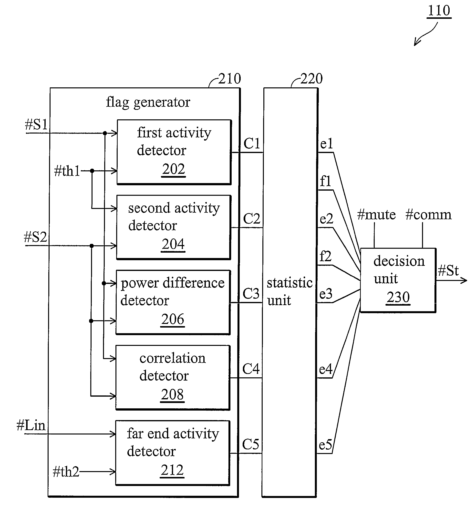
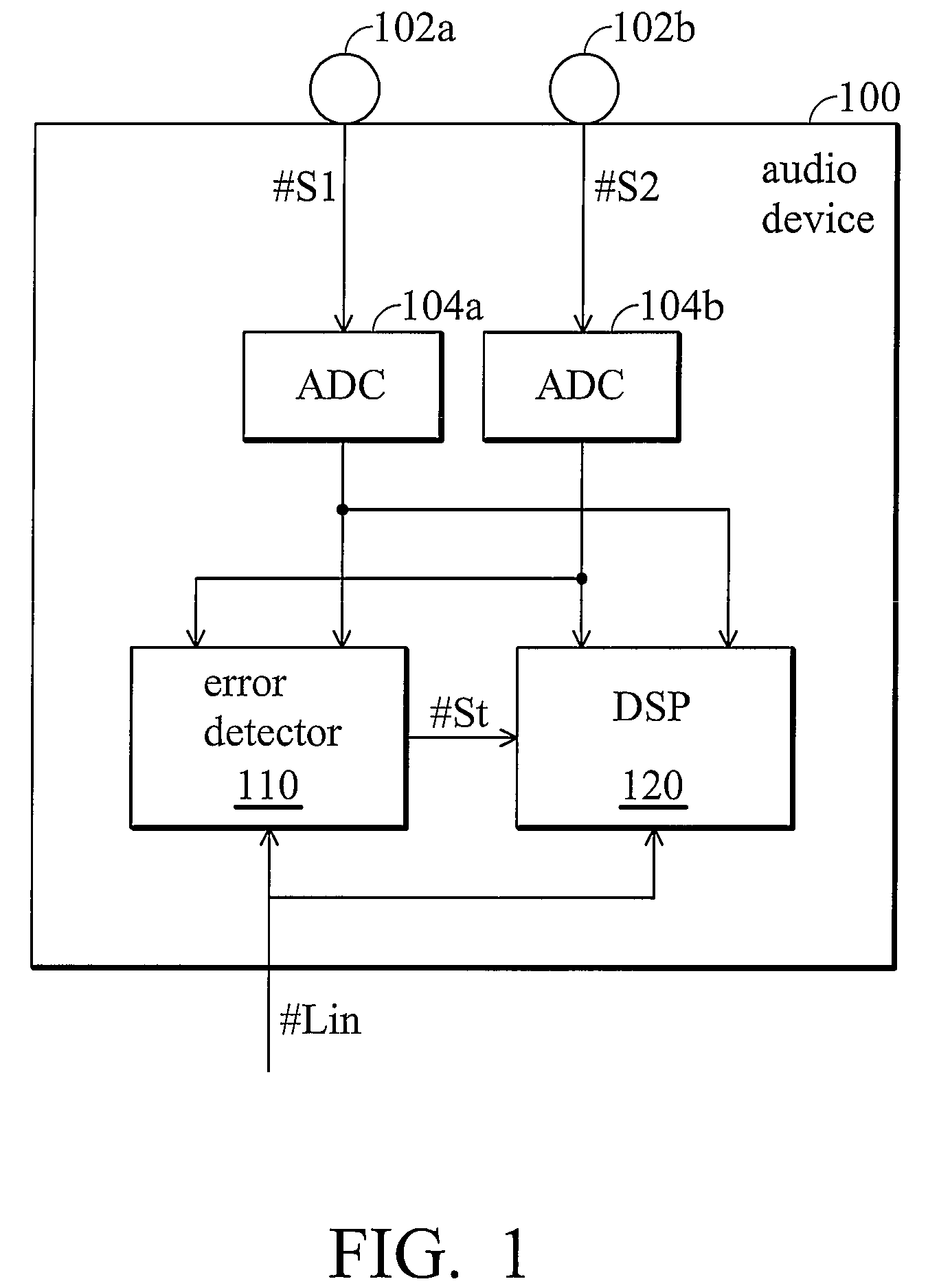
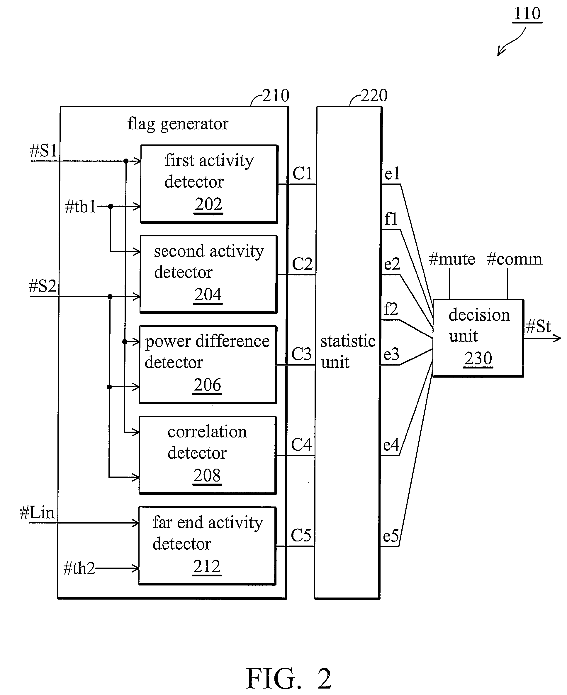
[0026]FIG. 1 shows an embodiment of an audio device 100 comprising an error detector 110 according to the invention. In the audio device 100, a microphone array is formed by a first microphone 102a and a second microphone 102b for receiving ambient audio signals. A first audio signal #S1 and a second audio signal #S2 respectively observed by the first microphone 102a and the second microphone 102b are digitized by a first analog to digital converter (ADC) 104a and a second ADC 104b and then processed in the DSP 120. The error detector 110 is an additional function block added by the invention, dedicated to detect functions of the first microphone 102a and the second mi...


PUM


Abstract

An audio device is provided, employing a defect detection method to detect defectiveness within a microphone array. The microphone array comprising a first microphone and a second microphone, respectively, generates a first audio signal and a second audio signal from ambient audio signals. An error detector is provided to detect functions of the first and second microphones based on the first and second audio signals to generate a status signal. A digital signal processor (DSP) processes the first and second audio signals based on the status signal. If the status signal indicates that only the first microphone or the second microphone is defective, the DSP switches to a single microphone mode in which only the remaining normal microphone is enabled. If the status signal indicates that both the first and second microphones are defective, the DSP generates an error indication signal and stops processing the first and second audio signals.

Description

BACKGROUND OF THE INVENTION[0001]1. Field of the Invention[0002]The invention relates to microphone arrays, and in particular, to defect detection of a microphone array utilized in an audio device.[0003]2. Description of the Related Art[0004]Microphone arrays are widely used in audio processing apparatuses for distinguishing desired audio signals from ambient noises. During ordinary usage, however, one or more microphones within a microphone array may be defective. As known, audio signals received by a microphone array are sent to a digital signal processor (DSP) for processing, such as a beam forming process or noise reduction process. If one microphone within the microphone array is defective, the beam forming process may render unpredictable results, whereby the audio quality would be degraded. Conventionally, there is no efficient method to detect that a microphone in a microphone array may be defective. As a result, as the number of microphones in a microphone array increases, ...

Claims


Application Information

Patent Timeline
Patent Type & Authority Patents(United States)
IPC IPC(8): H04R3/00H04R29/00
CPCH04R29/005
Inventor ZHANG, MING
Owner FORTEMEDIA
Why Eureka
Try Eureka