Multi-mode radio transmission system

a radio transmission system and multi-mode technology, applied in the direction of automatic exchange, substation equipment, electrical equipment, etc., can solve the problem that the best solution for radio terminal integration is not the method

Inactive Publication Date: 2003-10-21
NAT INST OF INFORMATION & COMM TECH
View PDF27 Cites 151 Cited by
  • Summary
  • Abstract
  • Description
  • Claims
  • Application Information

AI Technical Summary

Problems solved by technology

However, in conventional concept of software radio, we often change all the configuration programs for a radio communication system whenever a radio transmission system must be changed.
Therefore from the viewpoint of cost and miniaturizing, the method is not the best solution for the integration of radio terminal.

Method used


Image

  • Multi-mode radio transmission system
  • Multi-mode radio transmission system
  • Multi-mode radio transmission system

Examples


example-1

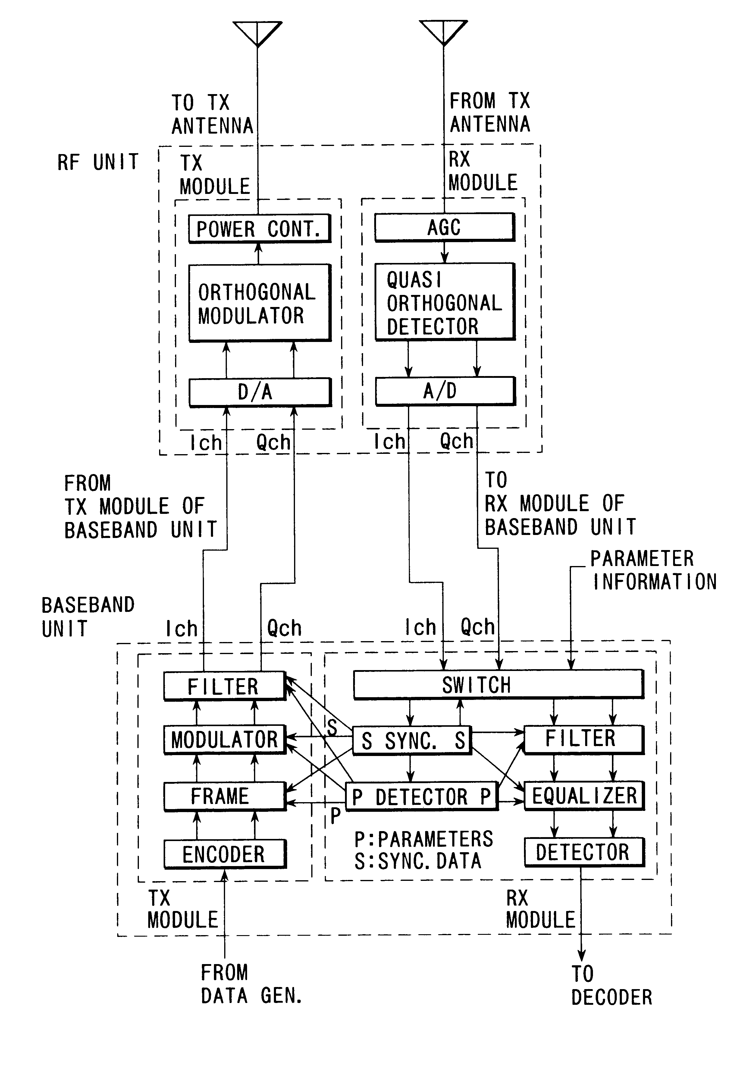
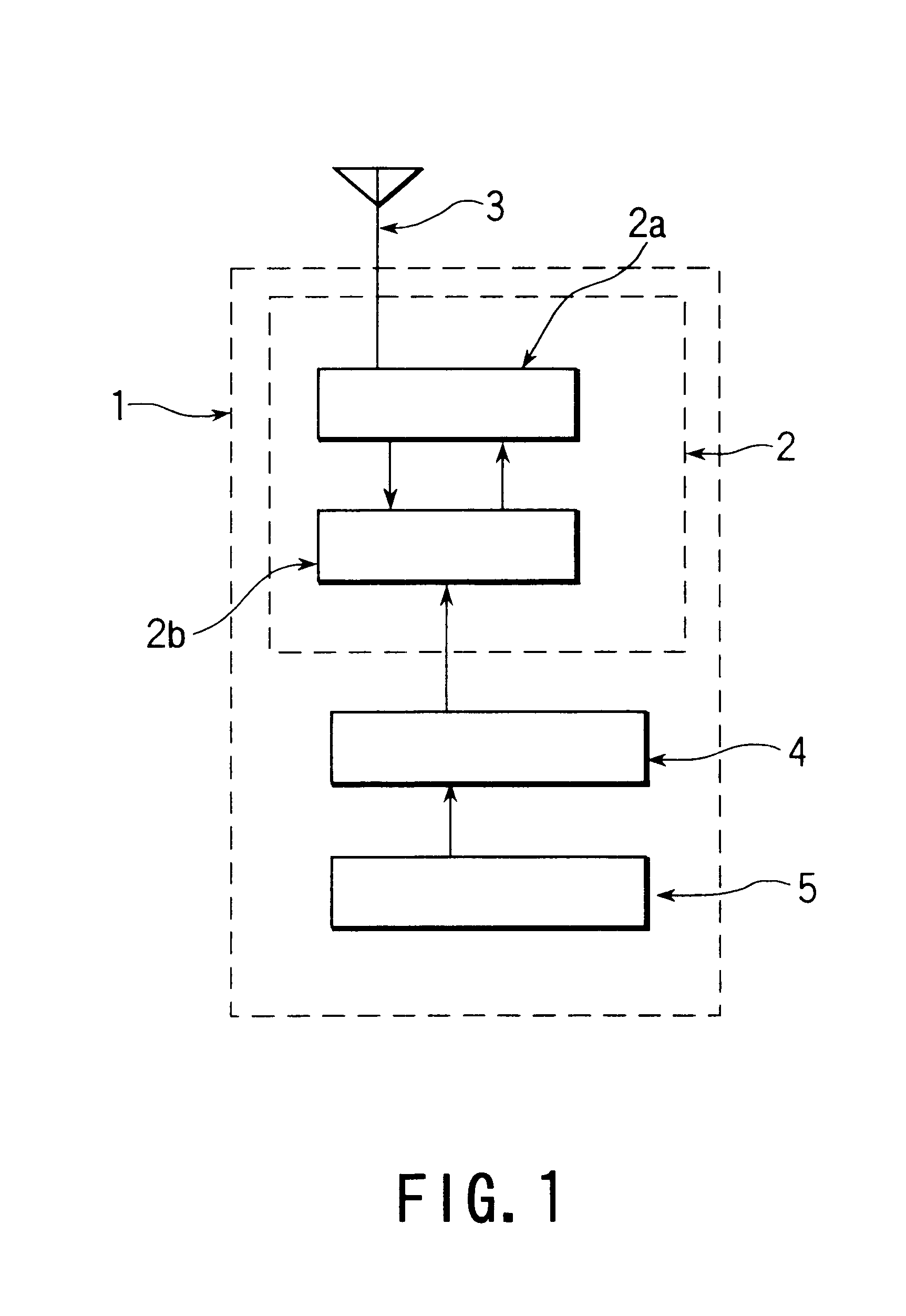
FIG. 1 is a functional block diagram for radio terminal used to a radio transmission system as example-1 and a radio terminal 1 have a communication terminal 1, a functional means 2, antenna 3, and a selective information specified means 5.

Accordingly, the communication functional means 2 is an unit to have the common modulation and demodulation function part 2a assembling common functional part a common function for each communication mode (for example, an orthogonal phase modulator, an automatic gain control part for receiving a signal, quasi-synchronized detecting part and the like) and the reconfiguable modulation and demodulation function part 2b comprising a function (for example, a shape of a filter, a format for transferring a signal and the like) possible not to be common.

The communication functional means 2 is set so as to a specific communication system by means of activating only a functional realizing means within the reconfigurable modulation and demodulation part 2b, ...

example-2

In the example-1, a basic system was described.

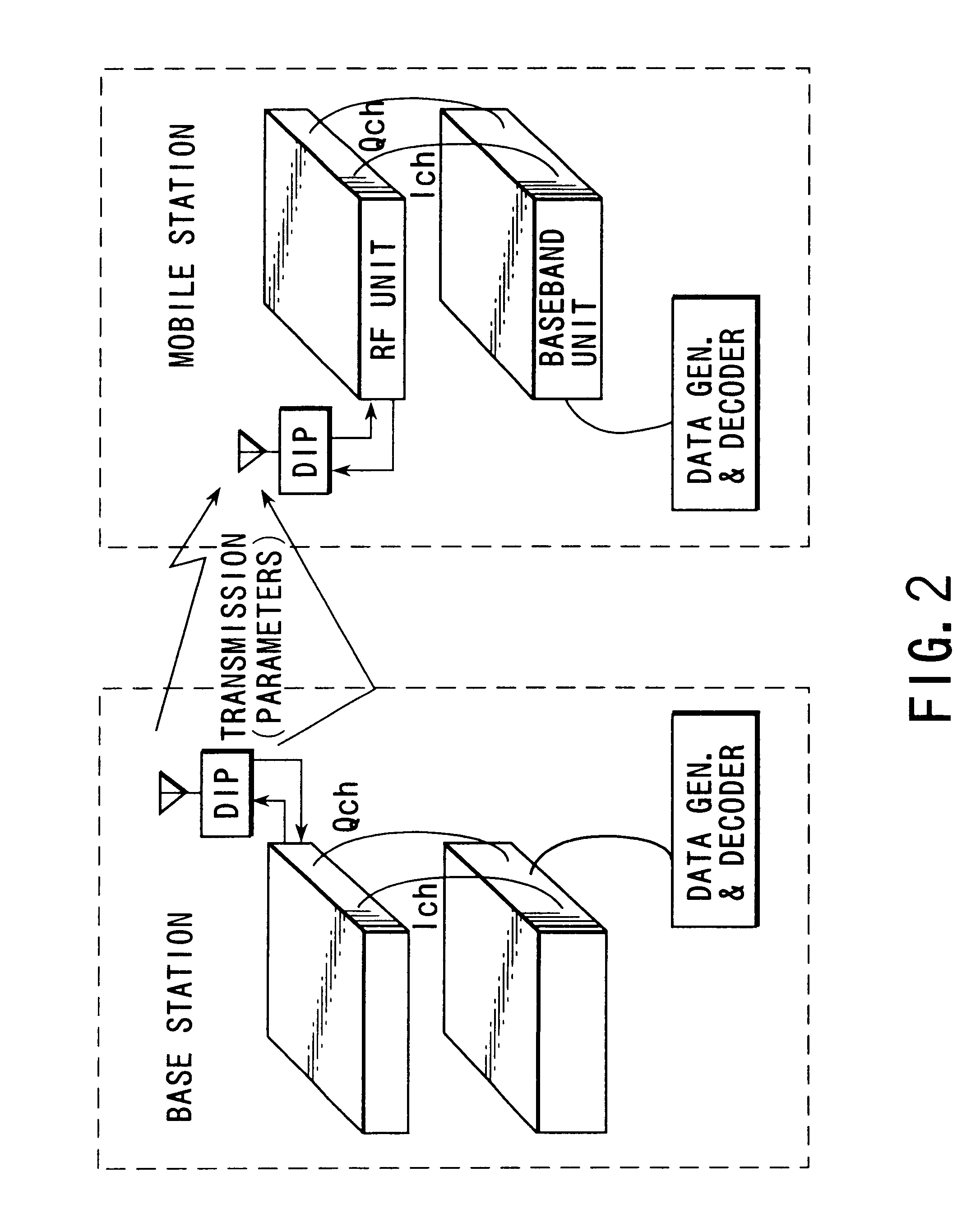
FIG. 2 is an approximate configuration for a radio transmission system to transmit a differential information from a base station to a mobile station.

In this example-2, a differential information, that is a selective information, from a radio base station is transmitted with the use of a radio broadcasting type, then mobile stations receiving the differential information establish modulation and demodulation scheme which the base station adopted.

Finally, the both stations start to communicate each other.

As a differential information to transmit with the use of this radio broadcasting, only an coefficient information such as tap coefficient for a filter, a coefficient to determine a shape of a filter, a coefficient to determine a tap coefficient for the sake of an equalization, (in the case of carrying out Fourier transformation at a receiving side) a coefficient to determine a length of FFT code sequence information (for CDMA) and the l...

example-3

FIG. 4 is a functional block diagram in a radio transmitting system referring to example-3 so as to store a differential information at a terminal side.

In the present example, a differential information referring to modulation and demodulation scheme for the use of communication apparatuses of each company is stored in the form of database at a radio terminal side. Moreover, the present example is multi-mode mobile communication system, in which a user can utilize systems for a plurality of companies only with the use of a switch attached to a portable telephone, of driving type with a user.

In the difference between the present example and abovementioned example-2, database, in which a differential information for the use of communication apparatuses of each company is input, are input beforehand. For example, a corresponding differential information for the use of communication apparatuses is input from data base to base-band unit as data and a synchronizing information to constitu...


PUM


Abstract

In order to utilize several radio communication systems with a radio terminal 1, by preparing the common modulator and demodulator part 2a and reconfigurable modulator and demodulator part 2b in advance and performing function selection means 4 with specified means of differential information 5 which information consists of the list of differential specification information of each radio communication system such as the tap coefficients of filter, frame format and the like, and their hardware address to allocate the information into digital signal processing hardware, the required radio communication systems are realized as users like.

Description

1. Field of the InventionThe present invention relates to a multi-mode radio transmission system under environment available by means of a different radio communication mode.2. Description of the Prior ArtIn the present radio communication systems such as land mobile communication systems broadcasting systems, and satellite communication systems, a common transmission mode has not been determined, and a communication system is utilized on the basis of various standards.For example, nowadays, in Japan, as digital mobile communication systems, PDC(Personal Digital Cellular) system and PHS(Personal Handy Phone) system are available. Moreover, even in Europe, GSM(Global System for Mobile Communications) system and the like has been operated.These systems looks different each other, however these systems are based of Quadrature modulation.As shown in FIG. 7, the Quadrature modulation is a method which can improve the transmission capacity more than two times with the use of two orthogona...

Claims


Application Information

Patent Timeline
Patent Type & Authority Patents(United States)
IPC IPC(8): H04Q7/32H04W88/02H04W88/06
CPCH04W88/06H04B1/06
Inventor HARADA, HIROSHIFUJISE, MASAYUKI
Owner NAT INST OF INFORMATION & COMM TECH
Why Eureka
Try Eureka