Supercharge Your Innovation With Domain-Expert AI Agents!

Steam iron comprising a smoothing brush

a technology of steam iron and smoothing brush, which is applied in the field of steam iron, can solve the problems of low steam flow rate at the outlet of the smoothing brush, affecting the proper penetration of steam into fabrics, and unable to precisely treat clothing areas, etc., and achieves the effect of increasing the steam flow ra

Active Publication Date: 2013-03-05
SEB SA
View PDF13 Cites 7 Cited by
  • Summary
  • Abstract
  • Description
  • Claims
  • Application Information

AI Technical Summary

Benefits of technology

[0009]To this end, the object of the invention is a steam iron comprising a boiling compartment for producing a steam flow and a steam distribution circuit with a smoothing brush having a head equipped with at least one hole for emitting steam, characterized in that it comprises a steam flow acceleration device by generating a puff of air that increases the flow rate of the steam at the outlet of the smoothing brush.

Problems solved by technology

However, such an iron has a boiling compartment that supplies steam at atmospheric pressure, resulting in a low steam flow rate at the outlet of the smoothing brush that is detrimental to the proper penetration of steam into fabrics, particularly for thick clothing.
In addition, the low speed of the steam at the outlet of the smoothing brush prevents the proper direction of the steam jet, making it impossible to precisely treat the areas of clothing that are to be smoothed, or to treat clothing arranged horizontally, since the steam naturally has a tendency to rise upwards, whereas the smoothing brush is oriented downwards.
Finally, such irons with boiling compartments operating at atmospheric pressure exhibit the disadvantage of having an irregular flow of steam at the outlet of the smoothing brush, with phases of very low steam flow following phases of high steam flow.

Method used


Image

  • Steam iron comprising a smoothing brush
  • Steam iron comprising a smoothing brush
  • Steam iron comprising a smoothing brush

Examples


Embodiment Construction

[0032]Only the elements necessary for understanding the invention are shown. To facilitate the reading of the drawings, the same elements bear the same references from one figure to another.

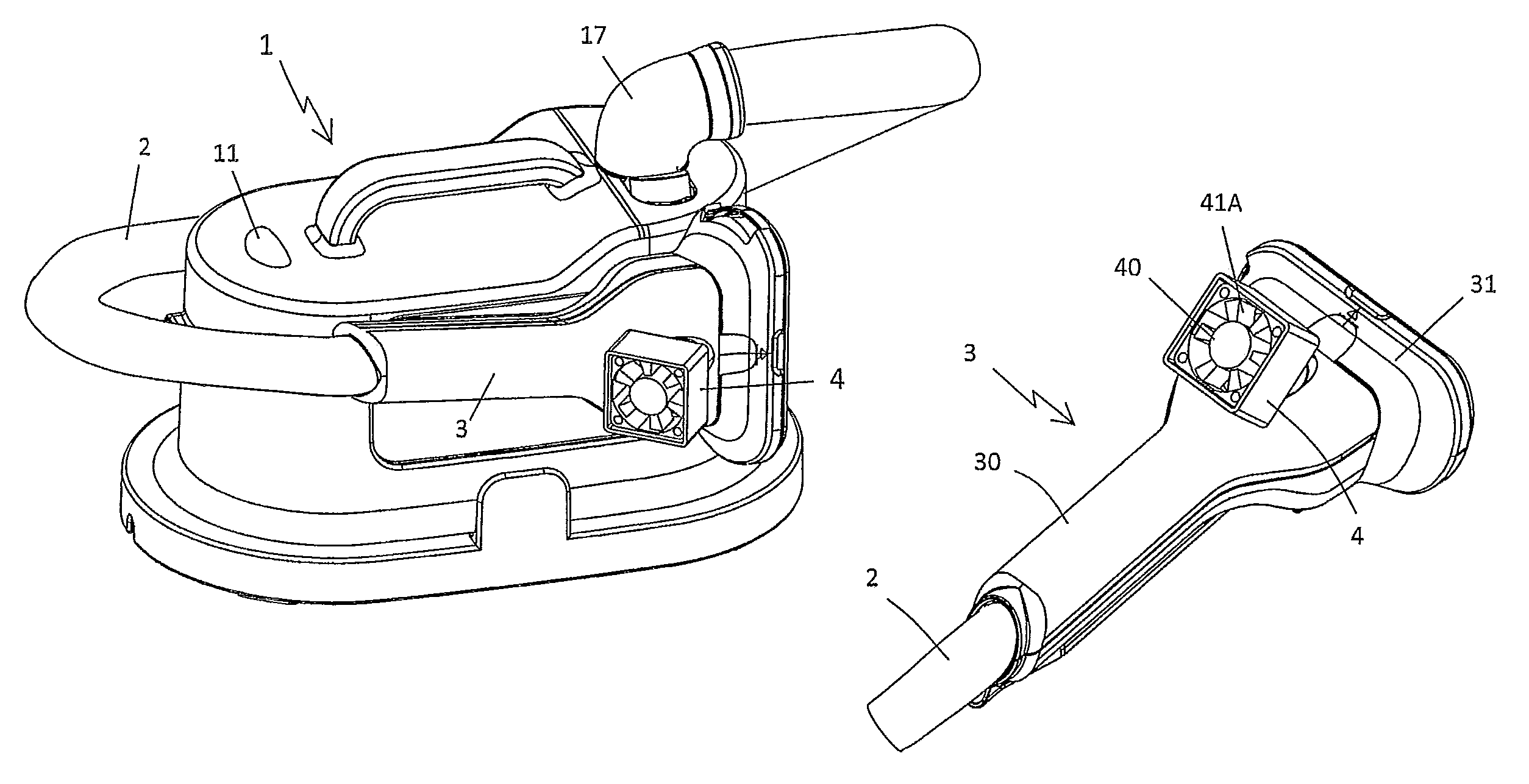
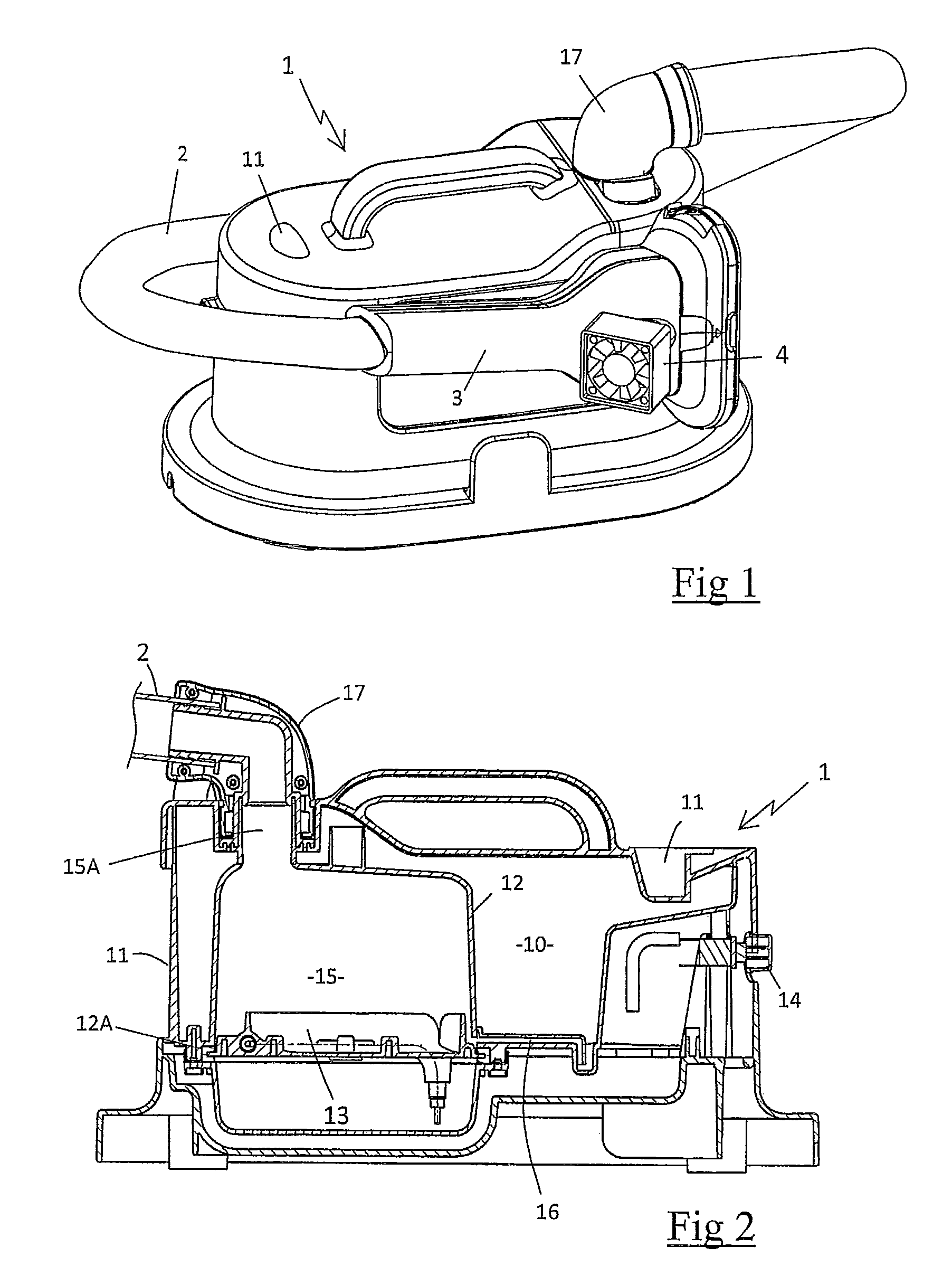
[0033]FIG. 1 shows a steam iron comprising a base 1 for generating steam connected by a flexible conduit 2 to a smoothing brush 3, said base 1 being similar to that described in greater detail in patent application FR 2 912 429.

[0034]In accordance with FIG. 2, the base 1 comprises an top side with a filling aperture 11 opening into a water tank 10, said tank 10 containing a boiling compartment 15 of limited volume in the shape of a bell 12 projecting into the bottom of the tank 10 and having a lower end resting against a seal 12A extending around a heating body 13. The heating body 13, which is advantageously made of aluminum, encloses a 1500 watt U-shaped resistor traditionally powered by a circuit with a thermostat that is not visible in the figures and a switch 14 to interrupt the electrical s...


PUM


Abstract

A steam iron having a boiling compartment (15) for producing steam and a steam distribution circuit with a smoothing brush (3) including a head (31) equipped with at least one hole (32) for emitting a flow of steam, characterized in that it contains a steam flow acceleration device (4) that generates a puff of air to increase the steam flow rate at the outlet of the smoothing brush (3).

Description

BACKGROUND OF THE INVENTION[0001]1. Field of the Invention[0002]The present invention relates to a steam iron comprising a boiling compartment for producing a steam flow and a steam distribution circuit with a smoothing brush equipped with at least one hole for emitting steam.[0003]2. Brief Description of the Prior Art[0004]French patent application FR 2 912 429 discloses a steam iron comprising a steam production device consisting of a boiling compartment with a heating body and a steam outlet through which steam can freely escape in the direction of a smoothing brush.[0005]Such an appliance offers the advantages of being inexpensive to manufacture and capable of quickly producing a saturating flow of steam that, when combined with a fiber brushing action, allows for a quick smoothing of curtains or clothing hanging vertically on a hanger.[0006]However, such an iron has a boiling compartment that supplies steam at atmospheric pressure, resulting in a low steam flow rate at the outl...

Claims


Application Information

Patent Timeline
Patent Type & Authority Patents(United States)
IPC IPC(8): D06F75/20D06F75/36
CPCD06F75/12D06F87/00D06F75/20
Inventor COMPEAU, JEAN-LOUISPACCAUD, DENISKREBS, MARTINSPATZ, DIERK
Owner SEB SA
Features
  • R&D
  • Intellectual Property
  • Life Sciences
  • Materials
  • Tech Scout
  • Unparalleled Data Quality
  • Higher Quality Content
  • 60% Fewer Hallucinations
Learn More