Completion method for horizontal wells in in situ combustion

a technology of in situ combustion and completion method, which is applied in the direction of fluid removal, earth-moving drilling, borehole/well accessories, etc., can solve problems such as catastrophic well failure, and achieve the effect of facilitating the extraction of hydrocarbons

Active Publication Date: 2013-03-05
CONOCOPHILLIPS CO
View PDF7 Cites 1 Cited by
  • Summary
  • Abstract
  • Description
  • Claims
  • Application Information

AI Technical Summary

Benefits of technology

[0005]In one embodiment of the present invention, an in situ combustion process in an underground reservoir having hydrocarbons, includes the steps of: (a) providing at least one injection well for injecting an oxidant into the underground reservoir, wherein the injection well is vertically displaced within the underground reservoir; (b) providing at least one production well having a substantially horizontal section and a substantially vertical section, wherein the distal end of the substantially horizontal section extending toward the injection well includes a toe portion at one end of the horizontal section closest to the injection well and a heel portion at the opposite end of the horizontal section, wherein the heel portion connects the horizontal portion to the vertical portion of the production well, wherein the toe portion is closer to the injection well than the heel portion; (c) injecting an obstructing agent into the substantially horizontal section of the production well, wherein the obstructing agent is a highly permeable granular material; (d) injecting the oxidant into the injection well to establish a combustion front of ignited hydrocarbons within the underground reservoir; and (e) propagating the combustion front through the underground reservoir to facilitate in obtaining hydrocarbons.

Problems solved by technology

The resulting production of hot, rapidly expanding, combustion gases through a small number of slots could cause a liner failure if the erosional velocity is exceeded, leading to sand production into the horizontal section and eventually a catastrophic production well failure.

Method used


Image

  • Completion method for horizontal wells in in situ combustion
  • Completion method for horizontal wells in in situ combustion
  • Completion method for horizontal wells in in situ combustion

Examples


Embodiment Construction

[0012]Reference will now be made in detail to embodiments of the present invention, one or more examples of which are illustrated in the accompanying drawings. Each example is provided by way of explanation of the invention, not as a limitation of the invention. It will be apparent to those skilled in the art that various modifications and variations can be made in the present invention without departing from the scope or spirit of the invention. For instance, features illustrated or described as part of one embodiment can be used in another embodiment to yield a still further embodiment. Thus, it is intended that the present invention cover such modifications and variations that come within the scope of the appended claims and their equivalents.

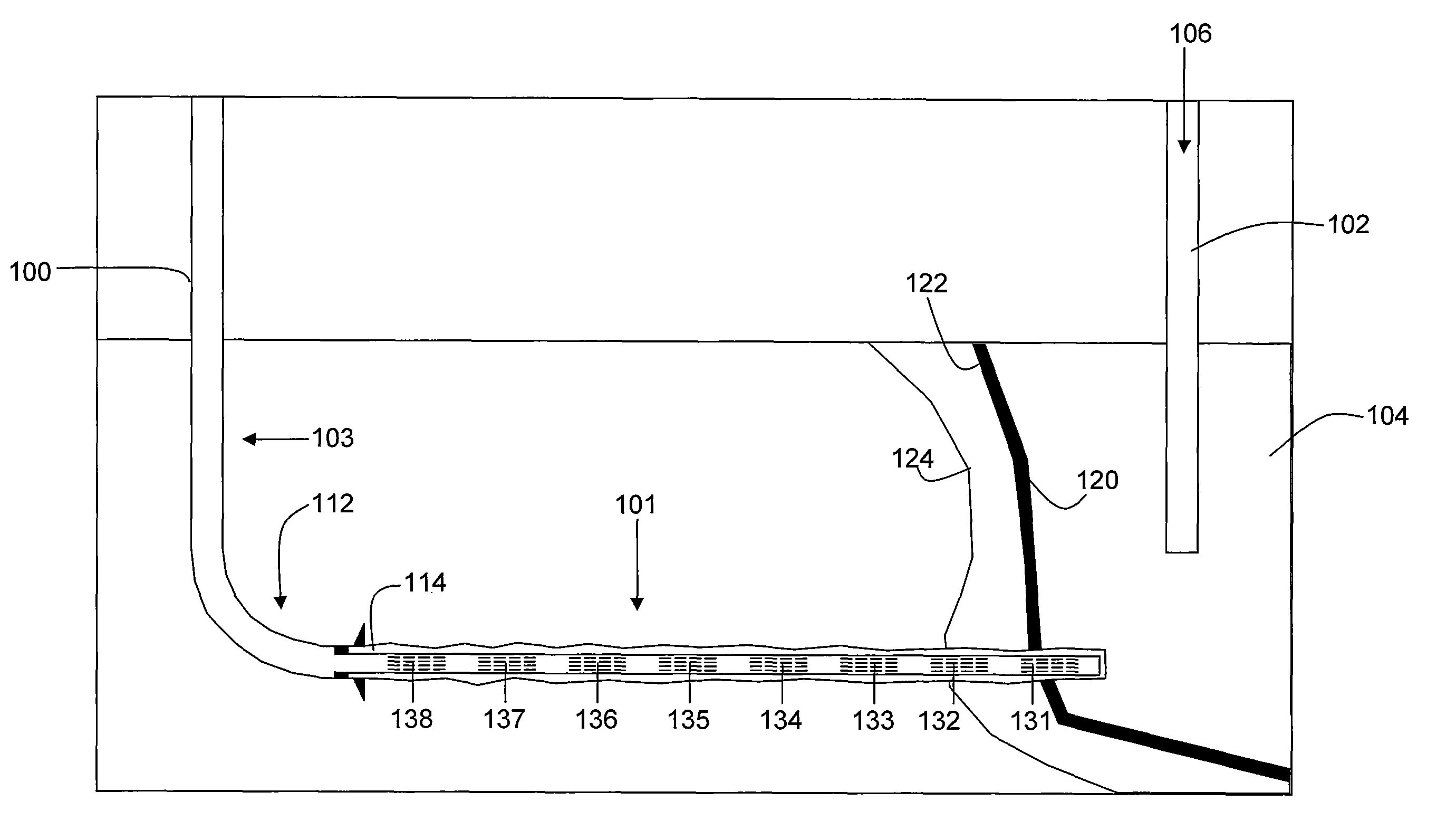
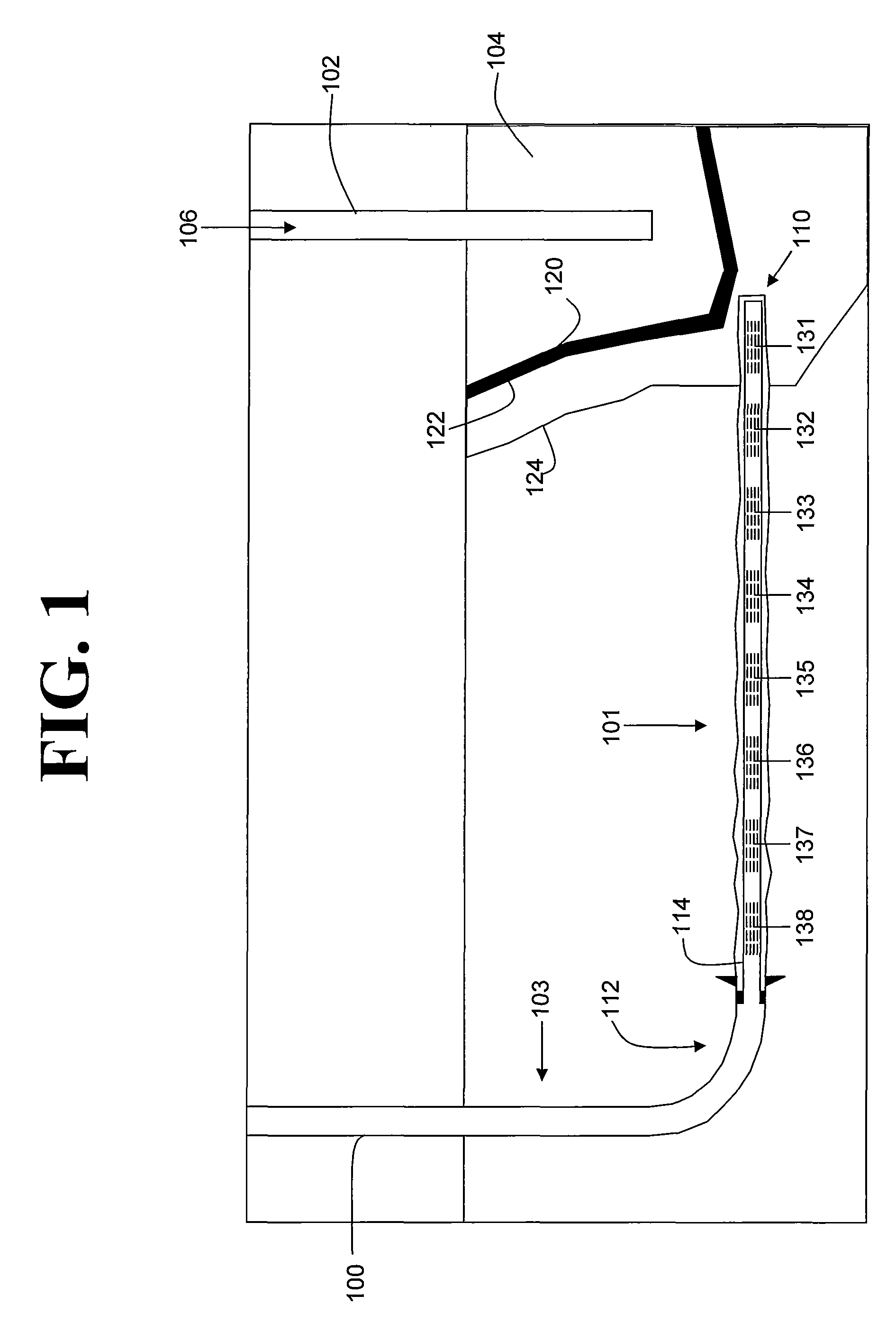
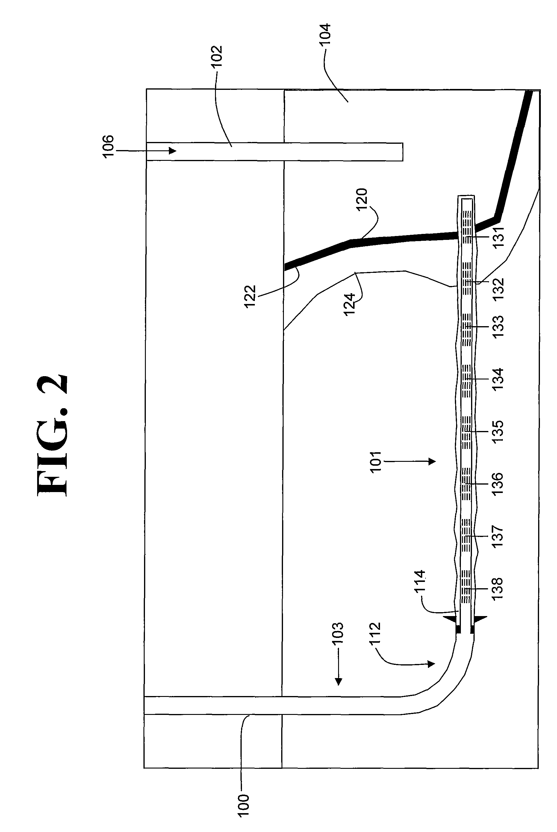
[0013]Referring to FIG. 1, an oil reservoir 104 contains an injection well 102 and a production well 100 having a horizontal section 101 and a vertical section 103. The production well 100 has the general shape of a foot, and is therefore de...


PUM


Abstract

An underground reservoir is provided comprising an injection well and a production well. The production well has a horizontal section oriented generally perpendicularly to a generally linear and laterally extending, upright combustion front propagated from the injection well. The method relates to controlling location of inflow into a production well during in situ combustion. The horizontal section of the production well includes blocking agents to prevent well failure.

Description

CROSS-REFERENCE TO RELATED APPLICATIONS[0001]This application claims priority benefit under 35 U.S.C. Section 119(e) to U.S. Provisional Patent Ser. No. 61 / 255,597 filed on Oct. 28, 2009 the entire disclosure of which is incorporated herein by reference.FIELD OF THE INVENTION[0002]Embodiments of the invention relate to a process for recovering hydrocarbons with in situ combustion.BACKGROUND OF THE INVENTION[0003]In situ combustion (ISC) processes are applied for the purpose of recovering oil from light oil, medium oil, heavy oil and bitumen reservoirs. In the process, oil is heated and displaced to an open production well for recovery. Historically, in situ combustion involves providing spaced apart vertical injection and production wells within a reservoir. Typically, an injection well is located within a pattern of surrounding production wells. An oxidant, such as air, oxygen enriched air or oxygen, is injected through the injection well into a hydrocarbon formation, allowing comb...

Claims


Application Information

Patent Timeline
Patent Type & Authority Patents(United States)
IPC IPC(8): E21B43/243E21B43/02
CPCE21B43/243
Inventor MENARD, WENDELL P.WHEELER, THOMAS J.DREHER, JR., WAYNE R.
Owner CONOCOPHILLIPS CO
Why Eureka
Try Eureka