
Gas laser discharge pre-ionization using a simmer-discharge

a pre-ionization and laser discharge technology, applied in the direction of laser details, electrical equipment, active medium materials, etc., can solve the problems of resonant frequency shift, increase of the difference between the resonant frequencies of lit and unlit discharge conditions, and resonant frequency shift, so as to avoid amplitude modulation of laser output pulses

Active Publication Date: 2013-03-05
COHERENT INC
View PDF35 Cites 4 Cited by
  • Summary
  • Abstract
  • Description
  • Claims
  • Application Information

AI Technical Summary

Benefits of technology

[0019]This method is particularly effective when the lasing pulses are delivered in a regular sequence thereof having a PRF different from that of the simmer pulses. Suspension of delivery of the simmer pulses during delivery of the laser pulses avoids amplitude modulation of laser output pulses by the simmer pulses.

Problems solved by technology

This resonant frequency-shift presents a problem in the design of RF excited CO2 lasers, as the frequency of the RF supply to the electrodes must be selected to provide a compromise between optimum ignition effectiveness and efficiency of operation once the discharge is ignited (lit).
The problem is complicated by the fact the longer a discharge is not lit the more difficult it is to reignite the discharge.
A limitation of the approaches referenced above is that as the area of the discharge increases, i.e., the area of the discharge electrodes increases, the difference between the resonant frequencies of the lit and un-lit discharge conditions increases.
This places a difficult design burden in providing an adequate bandwidth to accommodate the frequency difference.
These add cost and complexity to a laser.
Further, the approach presents a problem inasmuch as the lifetime of the laser is compromised by ablation of the electrode material into the laser gas mixture.
These improvements, however, still require a separate power supply and a hermetically sealed penetration into the gas enclosure of the laser.
A large VSWR can damage the power supply if the power supply is not turned off.
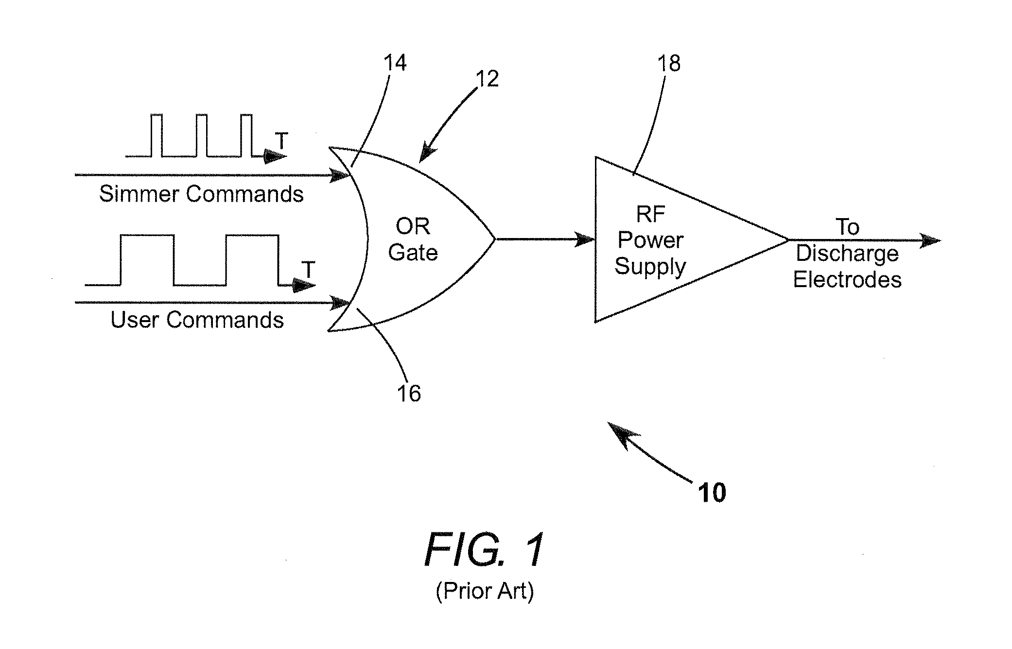
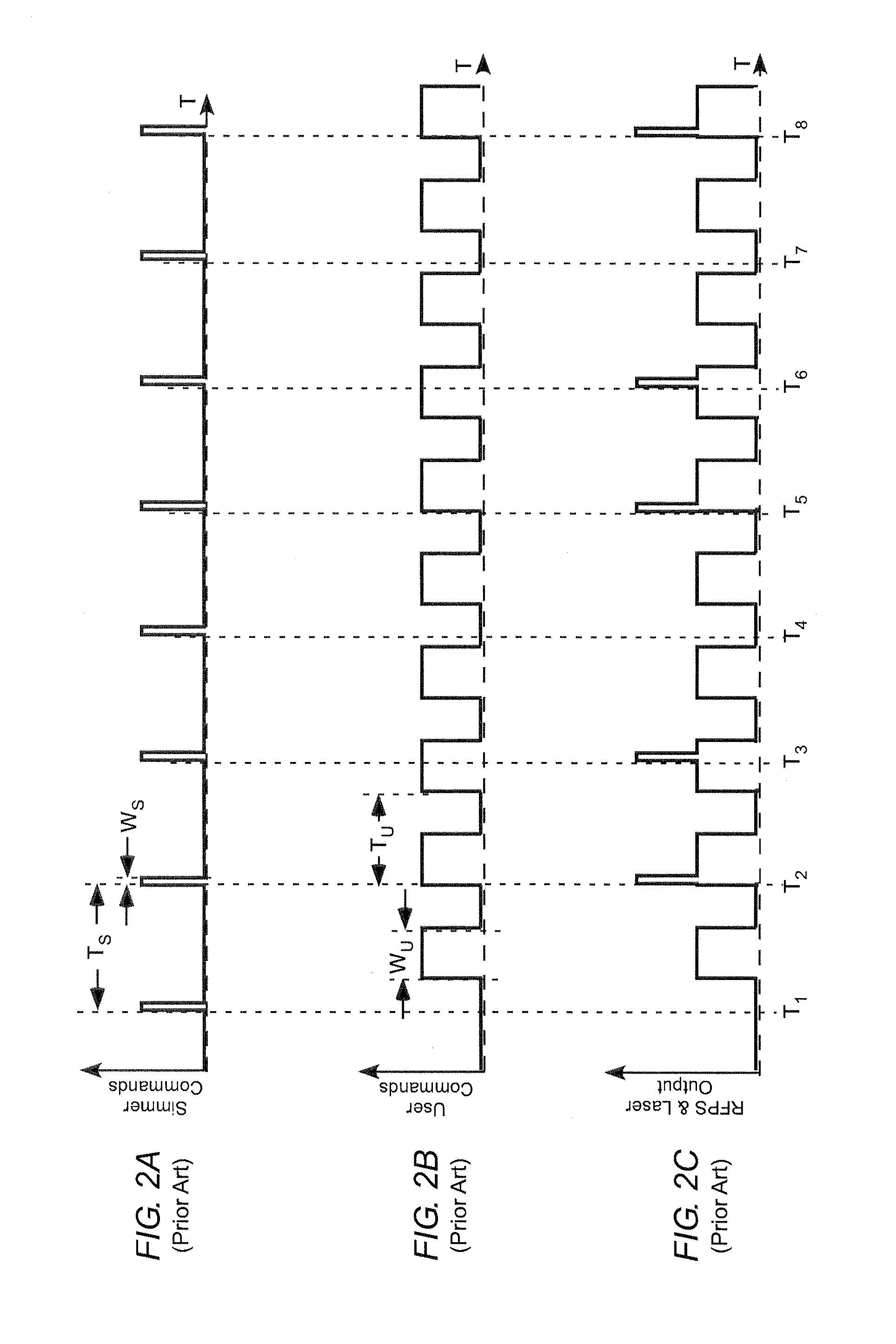
One problem with the arrangement of FIG. 1 is that the delivery-frequency to OR-gate 12 of simmer pulses and user command pulses is typically asynchronous.
As the laser-discharge pulses cause laser output, the laser output power is increased during the period of delivery of the simmer pulse in combination with the laser-discharge pulse, as schematically depicted, causing unwanted amplitude modulation of the output pulses.
Pulse-width modulation is as undesirable as amplitude modulation in laser processing.

Method used


Image

  • Gas laser discharge pre-ionization using a simmer-discharge
  • Gas laser discharge pre-ionization using a simmer-discharge
  • Gas laser discharge pre-ionization using a simmer-discharge

Examples


Embodiment Construction

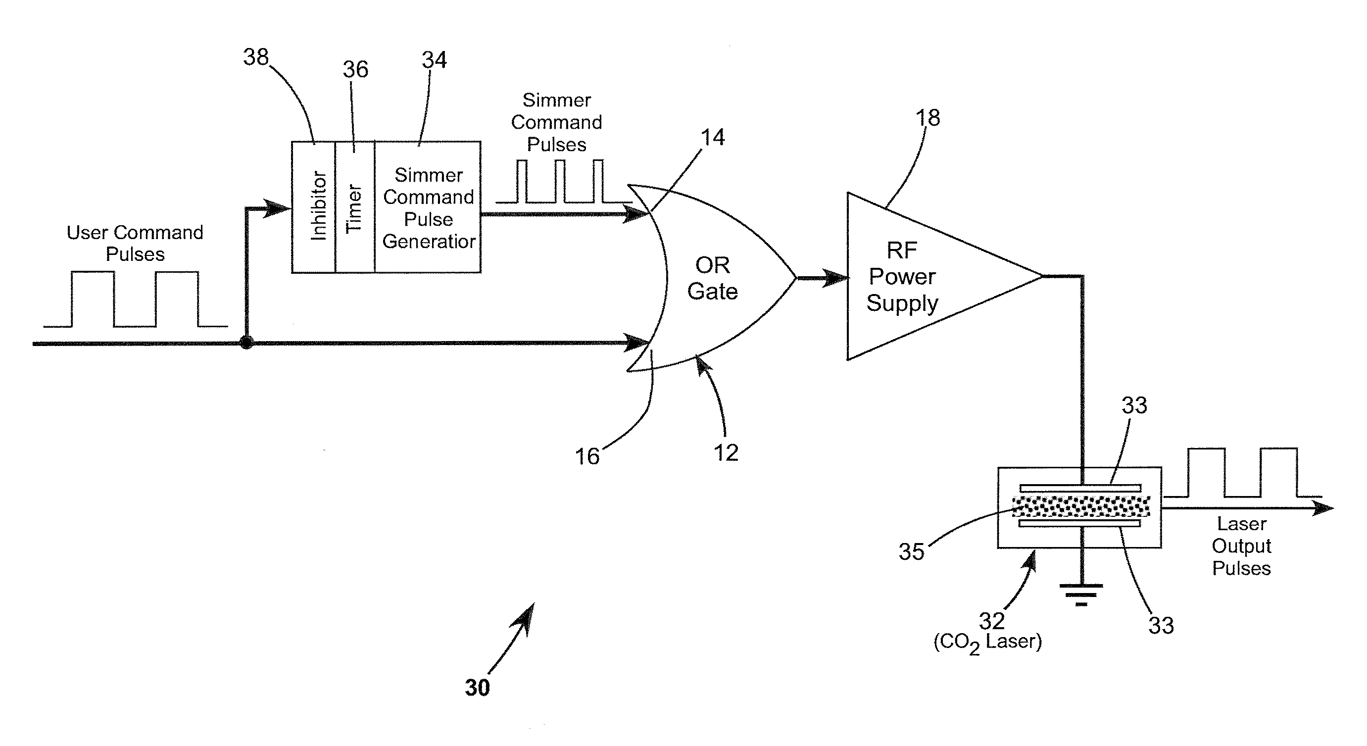
[0029]FIG. 3 schematically illustrates in block diagram form a preferred embodiment 30 of electronic circuitry in accordance with the present invention for providing pre-ionization of a laser discharge. The circuitry is arranged to drive a CO2 laser 32. Laser 32 includes discharge electrodes 33 having a lasing gas (gas-mixture) 35 therebetween. Those skilled in the electronics art, from the detailed description of the present invention set forth below, will understand that there are several means of implementing functions of the circuit blocks to which reference is made. Any of these means may be implemented without departing from the spirit and scope of the present invention. A detailed description of any such means is not required for understanding principles of the present invention and is not presented herein

[0030]Circuitry 30 includes a simmer command pulse generator 34 arranged to deliver to RF power supply 18 a train of simmer command pulses the PRF of which is determined by ...


PUM


Abstract

A gas discharge laser including a lasing gas between discharge electrodes and has a power supply for generating RF pulses to be delivered to the electrodes of the laser for energizing the lasing gas. A sequence of RF simmer pulses is delivered to the electrodes. The simmer pulses create sufficient free electrons in the lasing gas to facilitate subsequent ignition of the discharge while not causing laser action. RF lasing pulses having a longer duration than the simmer pulses are delivered to the electrodes to ignite the discharge and provide corresponding laser output pulses. Delivery of the simmer pulses is suspended during delivery of the lasing pulses to avoid amplitude or pulse-width modulation of the laser output pulses by the simmer pulses.

Description

PRIORITY[0001]The subject application claims priority to provisional application Ser. No. 61 / 147,199, filed Jan. 26, 2009, the disclosure of which is incorporated herein by reference.TECHNICAL FIELD OF THE INVENTION[0002]The present invention relates to pre-ionization methods and apparatus for facilitating ignition of a gas discharge. The invention relates in particular to igniting a gas discharge in a radio frequency (RF) excited, hermetically sealed carbon dioxide (CO2) laser.BACKGROUND[0003]RF-excited, hermetically sealed, pulsed CO2 lasers are gas discharge lasers widely used in material processing and laser machining applications such as via hole drilling in printed circuit boards and glass-plate scribing for TV screen manufacture. Such a laser includes a laser gas mixture including CO2 and inert gases. A gas discharge is ignited in the laser gas to energize the CO2 for providing optical gain. In order to be adaptable to a variety of applications, such a laser should be capable...

Claims


Application Information

Patent Timeline
Patent Type & Authority Patents(United States)
IPC IPC(8): H01S3/22H01S3/223
CPCH01S3/09705H01S3/09713H01S3/09702H01S3/2232
Inventor FONTANELLA, JOEL
Owner COHERENT INC
Learn More