
Conveying apparatus, recording apparatus, and conveying method

a technology of conveying apparatus and recording apparatus, which is applied in the directions of web handling, transportation and packaging, printing, etc., can solve the problem of a state in which further skewing is easy to occur, and achieves the effect of avoiding further skewing

Active Publication Date: 2013-03-12
SEIKO EPSON CORP
View PDF5 Cites 0 Cited by
  • Summary
  • Abstract
  • Description
  • Claims
  • Application Information

AI Technical Summary

Benefits of technology

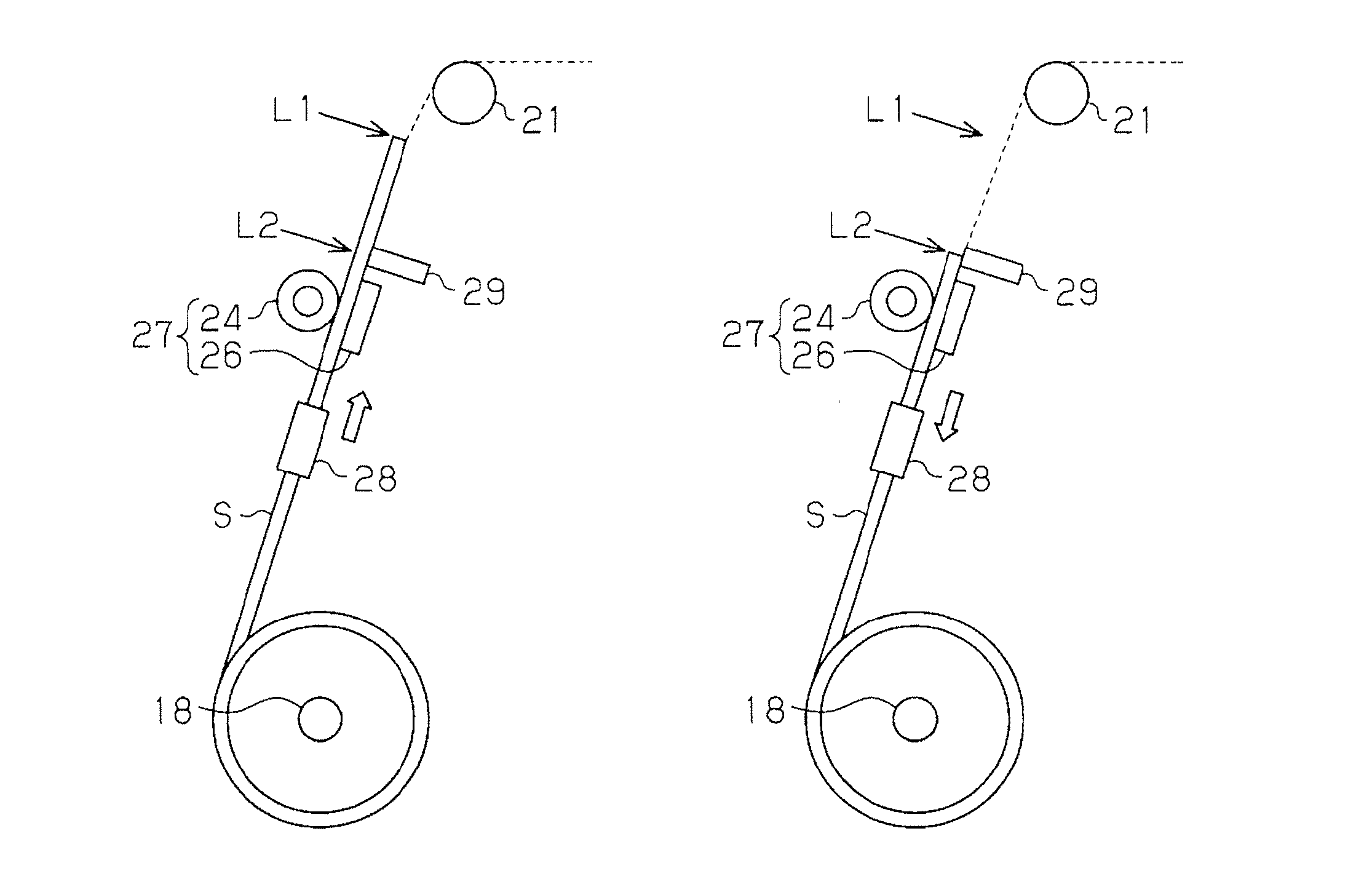
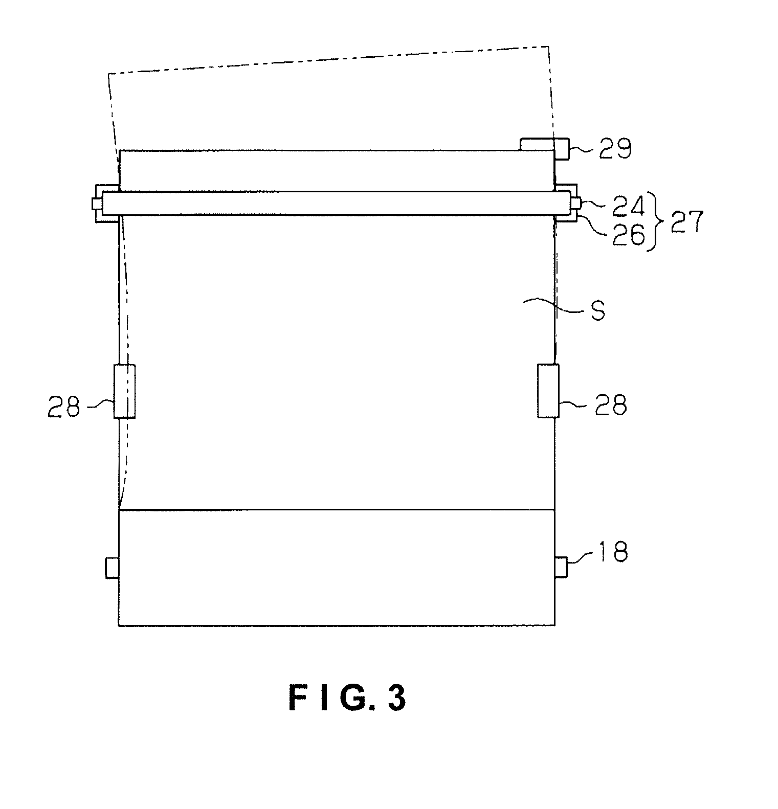
[0010]According to the aspect described above, the recording medium can be corrected to the proper conveyed orientation by conveying the rectangular recording medium in the reverse direction while tension is applied by the clamping unit and bringing the side ends of the recording medium in the width direction intersecting the conveying direction in contact with the guide member. Therefore, skewing of the recording medium can be corrected without shifting the shape of the leading edge of the recording medium to the left or right.
[0014]According to the aspect described above, since the controller performs skew correction on the basis of detection information on the leading edge of the recording medium sent from the detecting unit, the conveying of the recording medium in both the forward direction and the reverse direction can be stabilized.
[0018]According to the aspect described above, the same operational effects as those of the conveying apparatus described above can be achieved with the recording apparatus.
[0020]According to the aspect described above, it is possible to achieve the same operational effects as those of the conveying apparatus described above.

Problems solved by technology

However, the distal end of the recording medium is not necessarily perpendicular, and in cases in which skew correction is performed by bringing a recording medium whose distal end is not perpendicular in contact with the conveying rollers, there is a risk of creating a state in which further skewing readily occurs.

Method used


Image

  • Conveying apparatus, recording apparatus, and conveying method
  • Conveying apparatus, recording apparatus, and conveying method
  • Conveying apparatus, recording apparatus, and conveying method

Examples


Embodiment Construction

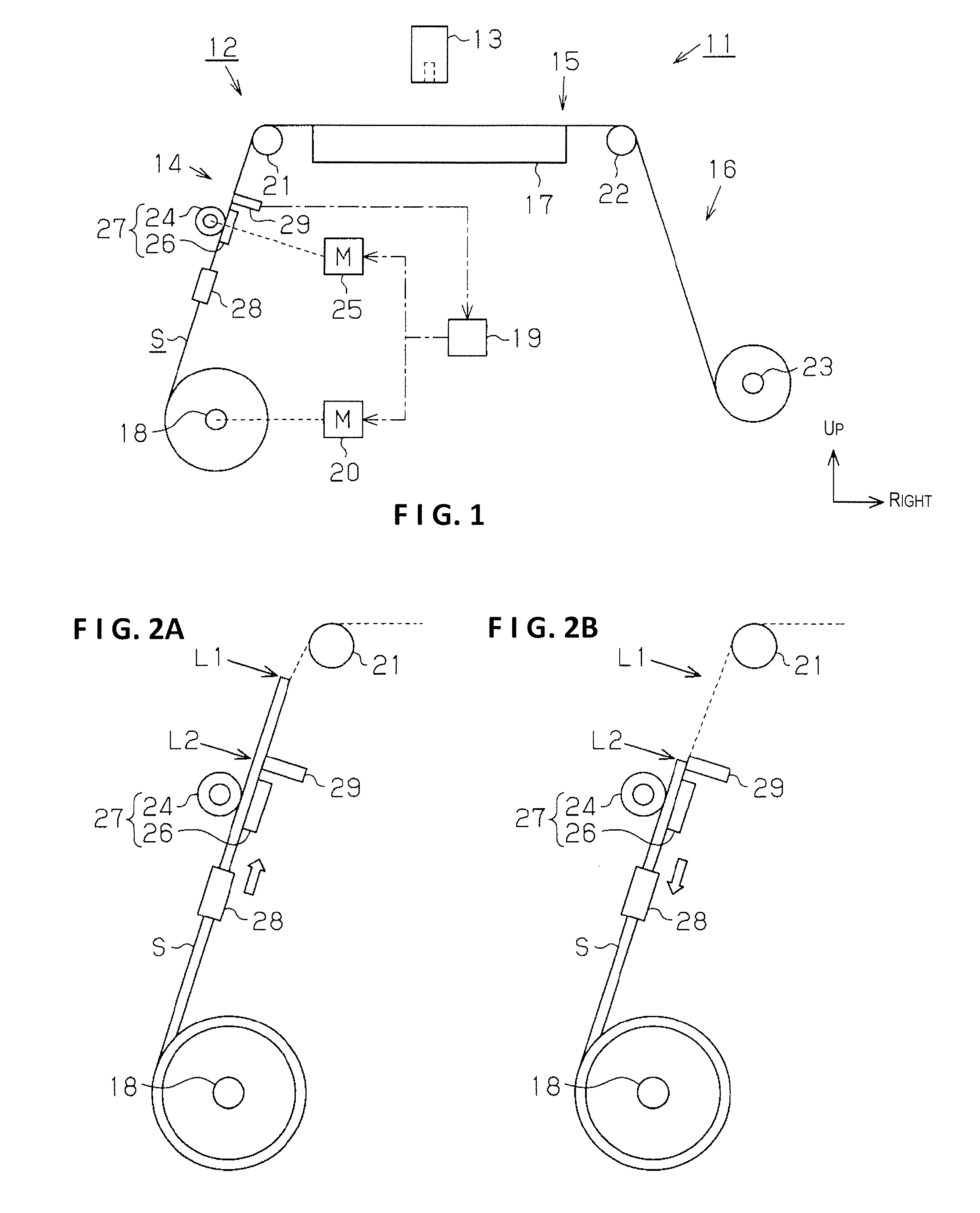
[0025]An embodiment is described hereinbelow according to FIG. 1, wherein the present invention is specified as an inkjet recording apparatus (hereinbelow shortened to “recording apparatus”), which is one type of a recording apparatus, and a target conveying apparatus (hereinbelow shortened to “conveying apparatus”) included in the same recording apparatus. In the description hereinbelow, when the “up-down direction” and the “left-right direction” are mentioned, they are referencing the “up-down direction” and the “left-right direction” in FIG. 1. Likewise, when the “forward-backward direction” is mentioned, “forward” refers to the foreground of the direction orthogonal to the image plane of FIG. 1, and “backward” refers to the background of the same direction.

[0026]A recording apparatus 11 comprises a conveying apparatus 12 for conveying continuous paper S as a rectangular recording medium, and a substantially rectangular recording head 13 disposed above the conveying apparatus 12 ...


PUM

PropertyMeasurementUnit
widthaaaaaaaaaa
shapeaaaaaaaaaa
tensionaaaaaaaaaa

Abstract

A conveying apparatus includes a holding part that holds a recording medium in the form of a roll and rotates, a clamping unit that clamps the recording medium downstream from the holding part along a conveying route, a regulating member that regulates a position of a side end of the recording medium in a width direction intersecting the conveying direction between the holding part and the clamping unit in the conveying route, a drive unit that rotatably drives the holding part in a forward direction to unwind the recording medium and a reverse direction to rewind the recording medium, and a controller that controls a drive state of the drive unit. The controller controls the drive unit so that, after the holding part is driven forward, the holding part is driven in reverse.

Description

CROSS-REFERENCE TO RELATED APPLICATIONS[0001]This application claims priority to Japanese Patent Application No. 2010-039140 filed on Feb. 24, 2010. The entire disclosure of Japanese Patent Application No. 2010-039140 is hereby incorporated herein by reference.BACKGROUND[0002]1. Technical Field[0003]The present invention relates to a conveying apparatus, a recording apparatus, and a conveying method.[0004]2. Related Art[0005]Conventionally, in a recording apparatus which performs recording on a conveyed recording medium, to prevent recording from being performed in a state in which the distal end of the recording medium is at an incline, skew correction for correcting the skew (the oblique movement) of the recording medium is performed just before (upstream) recording is performed (Japanese Laid-Open Patent Application No. 2003-195424, for example).[0006]In the recording apparatus according to Japanese Laid-Open Patent Application No. 2003-195424, the skew of the roll medium is corr...

Claims


Application Information

Patent Timeline
Patent Type & Authority Patents(United States)
IPC IPC(8): B41J29/38
CPCB65H20/02B65H2301/331B65H2403/942B65H2701/1311B65H2220/03B65H2220/01B65H2220/02
Inventor HABA, SHINJI
Owner SEIKO EPSON CORP
Learn More