Adhesive dispensing apparatus and image forming apparatus

a technology of adhesive dispensing and image forming, which is applied in the directions of book binding, transportation and packaging, packaging, etc., can solve the problems of high cost, large apparatus, and inability to transport a subsequent sheet bundle, so as to reduce the shift of the sheet bundle and increase the size of the apparatus or cost

Active Publication Date: 2007-02-01
NISCA KK
View PDF3 Cites 5 Cited by
  • Summary
  • Abstract
  • Description
  • Claims
  • Application Information

AI Technical Summary

Benefits of technology

[0010] In the adhesive dispensing apparatus and image forming apparatus of the present invention, the sheet bundle is transported with the edge having the adhesive dispensed thereto as the leading edge. Therefore, the edge of the sheet bundle does not contact the transport path during the transportation, and the adhesive is not scraped off. Accordingly, it is not necessary to provide a large space in a transport path, or provide a special device for strictly controlling an amount of the adhesive. It is possible to securely bind together each of the sheets of the sheet bundle and securely attach a cover sheet to the sheet bundle without increasing a size of the apparatus or cost. Also, the adhesive does not stick to a wall of the transport path, so that a subsequent sheet bundle is transported smoothly.
[0011] According to the present invention, an adhesive dispensing apparatus and image forming apparatus include support means for supporting a sheet bundle, dispensing means for dispensing an adhesive to an edge of the sheet bundle supported by the support means, cover sheet supply means for setting a cover sheet at a predetermined position, and transport means for transporting the sheet bundle with the edge having the adhesive dispensed by the dispensing means as the leading edge and for pressing the edge of the sheet bundle against the cover sheet set at the predetermined position. When the sheet bundle is transported using a rotating body such as a roller, a skew in a transport direction may be generated between sheets (during the transportation). In the adhesive dispensing apparatus and image forming apparatus, it is possible to correct the skew by pressing the edge of the sheet bundle against the cover sheet.
[0012] According to the present invention, the adhesive dispensing apparatus and image forming apparatus may further include moving means for moving the dispensing means between a first position where the adhesive is dispensed to the edge of the sheet bundle and a second position where the dispensing means does not hinder the transport means to transport the sheet bundle. With this configuration, instead of moving the sheet bundle to avoid the dispensing means, the dispensing means moves to ensure the transport path for the sheet bundle with the adhesive dispensed thereto, thereby reducing a shift of the sheet bundle after the adhesive is dispensed.

Problems solved by technology

If the adhesive is scraped off from the edge of the sheet bundle during the transportation, the sheet bundle may not be bound well or the cover sheet may not be attached to the sheet bundle.
Also, if the adhesive sticks to a wall of a transport path, it is difficult to transport a subsequent sheet bundle.
Accordingly, such an apparatus tends to be large and high cost.

Method used


Image

  • Adhesive dispensing apparatus and image forming apparatus
  • Adhesive dispensing apparatus and image forming apparatus
  • Adhesive dispensing apparatus and image forming apparatus

Examples


first embodiment

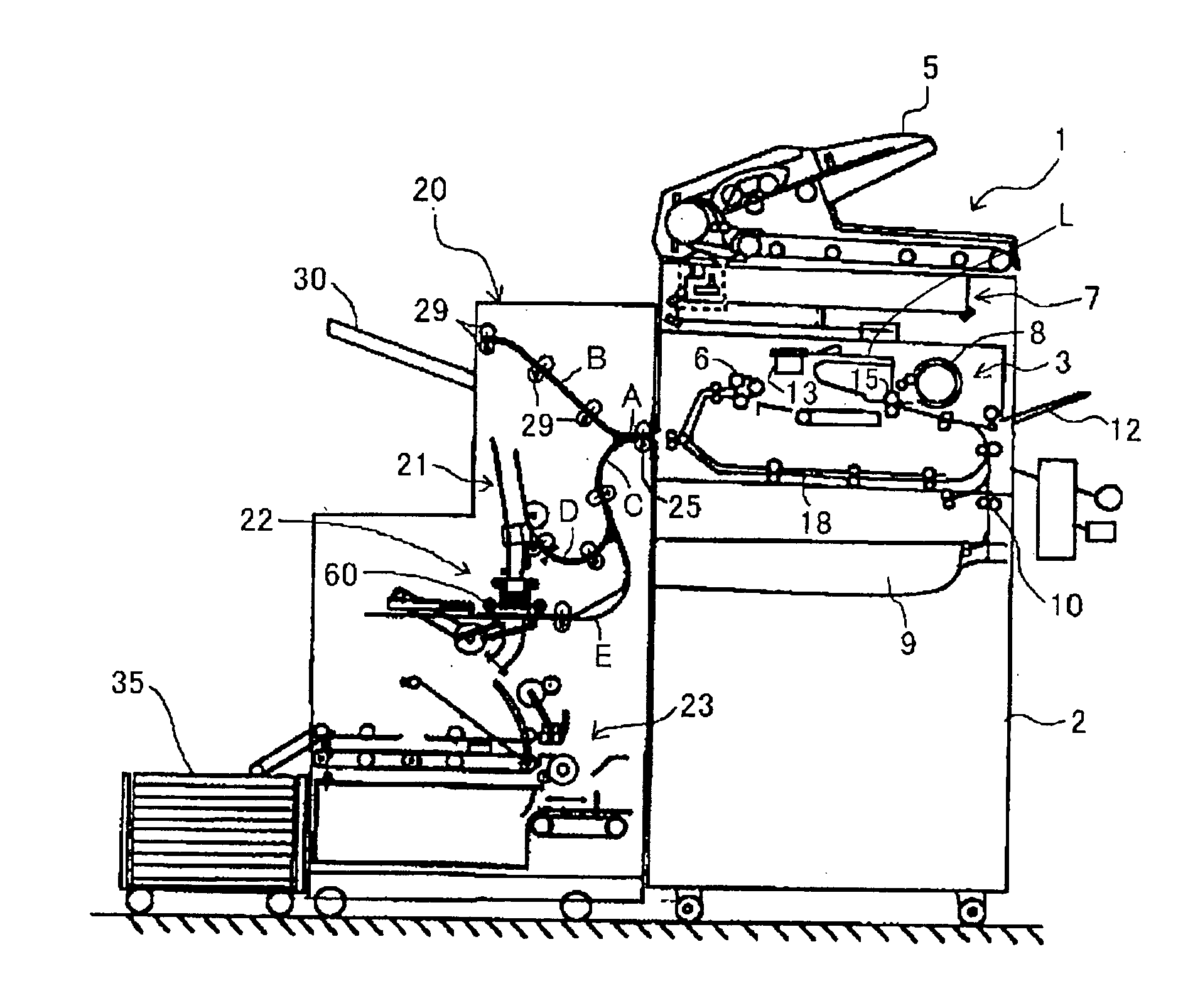
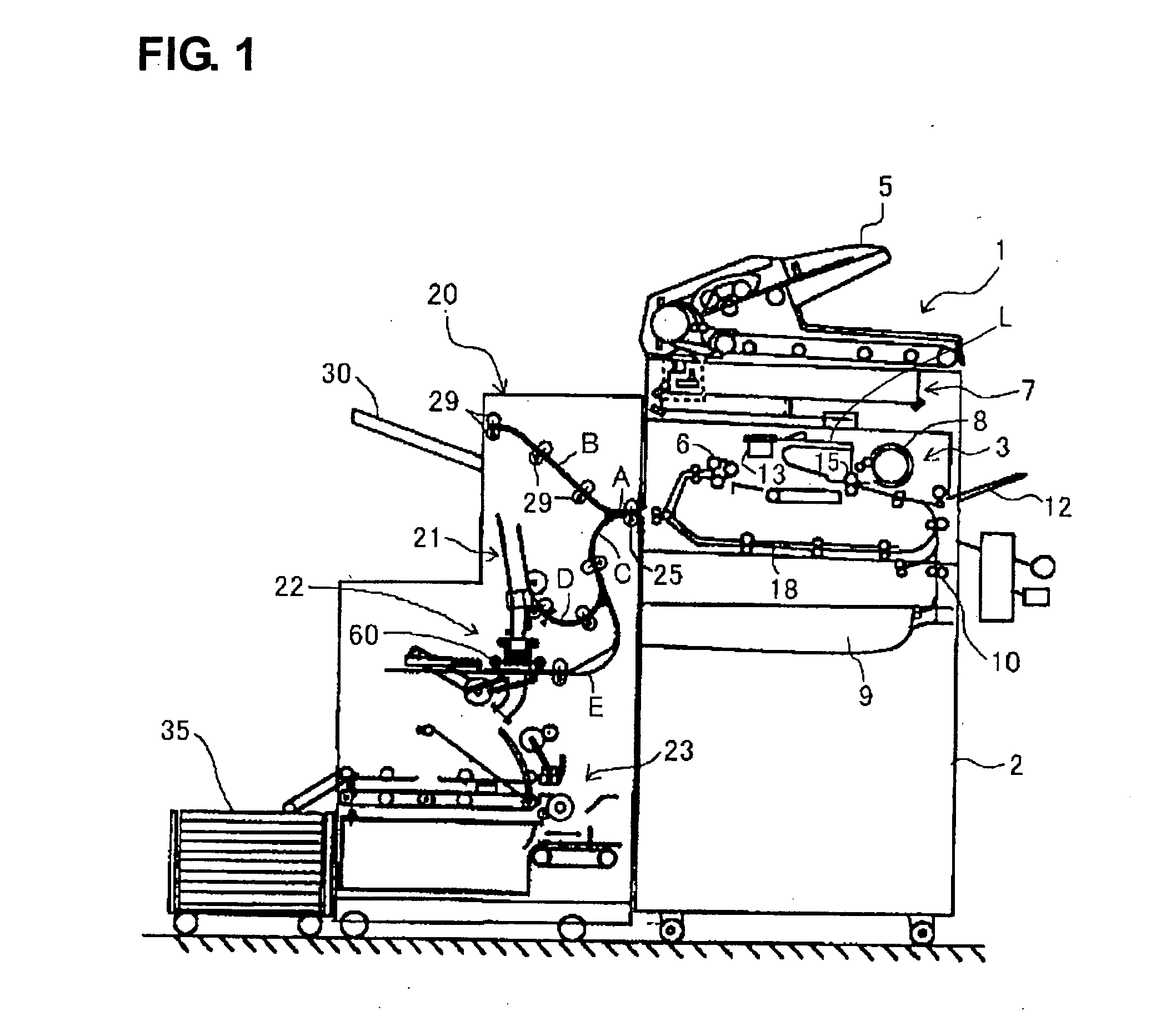
[0048] Hereunder, embodiments of the present invention will be explained with reference to the accompanying drawings. FIG. 1 shows a sheet processing apparatus 20 provided with an adhesive dispensing apparatus according to the present invention, and a copier 1 provided with the sheet processing apparatus 20 as an example of an image forming apparatus.

[0049] As shown in FIG. 1, an image forming unit 3 is disposed inside an apparatus main unit 2 of the copier 1. The image forming unit 3 forms images on sheets such as regular paper or OHP. Specifically, an original feeding apparatus 5 is mounted onto the top of the apparatus main unit 2. Originals automatically are fed from the original feeding apparatus 5, and are optically read by an optical reading means 7. The image information is converted into digital signals to be sent to the image forming apparatus 3.

[0050] In the image forming apparatus 3, laser light L from the optical irradiating means 13 is reflected to an outer surface of...

second embodiment

[0133]FIG. 26(a) to FIG. 29 show the sheet bundle transport mechanism for transporting the sheet bundle S1. The sheet bundle transport mechanism (transport means) comprises a plurality of paired bundle transport rollers 333 as abutting means for transporting the sheet bundle S1 while rotatably pressing both sides of the sheet bundle S1. The paired bundle transport rollers 333 nip the both sides of the sheet bundle S1 and rotate to transport the sheet bundle S1 to the dispensing area 155 disposed below. The adhesive unit 66 moves to the dispensing area 155 where the adhesive is dispensed to the edge of the sheet bundle S1. When the adhesive is dispensed to the edge of the sheet bundle S1, the adhesive unit 66 moves to the idling position 156 or the refilling position 157 to form the transport path for the sheet bundle S1.

[0134] FIGS. 27(a) and 27(b) show a state that the paired bundle transport rollers 333 push the edge of the sheet bundle S1 against the cover sheet S0. After the adh...


PUM

PropertyMeasurementUnit
distanceaaaaaaaaaa
sizeaaaaaaaaaa
adhesiveaaaaaaaaaa

Abstract

An adhesive dispensing apparatus for dispensing an adhesive on a sheet bundle includes a support device for supporting the sheet bundle, a dispensing device disposed adjacent to the support device for dispensing the adhesive on an edge of the sheet bundle supported by the support device, and a transport device disposed adjacent to the support device for transporting the sheet bundle from the edge, to which the adhesive is applied, as a leading edge in a transport direction. A refilling device is provided for refilling the adhesive to the dispensing device, and a moving device moves the dispensing device between a dispending position where the adhesive is dispensed to the edge of the sheet bundle and a refilling position where the adhesive is supplied to the dispensing device from the refilling device.

Description

CROSS-REFERENCE TO RELATED APPLICATION [0001] This is a continuation application of Ser. No. 10 / 795,268 filed on Mar. 9, 2004.BACKGROUND OF THE INVENTION AND RELATED ART STATEMENT [0002] The present invention relates to an adhesive dispensing apparatus for dispensing an adhesive to a bundle of sheets and an image forming apparatus provided with the adhesive dispensing apparatus. [0003] In general, a sheet processing apparatus such as a finisher equipped in a binding apparatus or image forming apparatus is able to perform a process of stitching a bundle of sheets after the sheets are bound in a bundle, and a process of dispensing an adhesive such as glue on an edge of a bundle of sheets. [0004] In such a process of dispensing an adhesive, the adhesive is dispensed on an edge of the bundle, and the bundle is transported in a direction along the edge thereof. Then, the sheet bundle is moved relative to a cover sheet in a direction perpendicular to the transport direction, so that the c...

Claims


Application Information

Patent Timeline
Patent Type & Authority Applications(United States)
IPC IPC(8): B32B37/12B32B38/14B42C1/12
CPCB42C1/12B65H2301/43827B65H2701/131Y10T156/1744Y10T156/1798Y10T156/172Y10T156/1749
Inventor TAKAGI, KATSUMASATAKAHASHI, MASAYAISHIMARU, SHUJIKONO, YOSHINOBUKOABAYASHI, MISAO
Owner NISCA KK
Why Eureka
Try Eureka