
Imaging apparatus

a technology of imaging apparatus and spherical tube, which is applied in the direction of optical radiation measurement, instruments, television systems, etc., can solve the problems of large apparatus, significant increase in cost, and inability to cope with the aforementioned wavelength range, so as to achieve the effect of not increasing the size of the apparatus

Inactive Publication Date: 2009-01-22
FUJIFILM CORP +1
View PDF7 Cites 72 Cited by
  • Summary
  • Abstract
  • Description
  • Claims
  • Application Information

AI Technical Summary

Benefits of technology

[0008]In view of the foregoing circumstances, it is an object of the present invention to provide an imaging apparatus that can form spectral images in a near-infrared region in addition to ordinary images without increasing the size of the apparatus and without significantly increasing the cost of the apparatus.
[0022]In the imaging apparatus of the present invention, the imaging unit can obtain an image of an observation target for each of at least the fourth light components and the fifth light components, at least two kinds of light components in different wavelength bands from each other in a near-infrared region. Further, the spectral image formation circuit can generate a spectral image signal in the near-infrared region. Therefore, it is possible to form a spectral image in the near-infrared region. Further, the light source unit can selectively output white light and light in a wavelength band that is different from that of the white light. Further, the first pixels can receive the first light components and the fourth light components by the first spectral devices, and the second pixels can receive the second light components and the fifth light components by the second spectral devices. Therefore, it is possible to perform imaging for the visible light region and imaging for the near-infrared region by using the same imaging device by temporally dividing the imaging operation (at different time from each other). Therefore, it is not necessary to separately provide an optical system for the visible light region and an optical system for the near-infrared region. Hence, it is possible to obtain ordinary images and spectral images in the near-infrared region without increasing the size of the apparatus and without significantly increasing the cost of the apparatus.

Problems solved by technology

In other words, the apparatus is not designed to cope with the aforementioned wavelength ranges, i.e., 600 to 1300 nm and 700 to 1300 nm.
Hence, there are problems that the size of the apparatus becomes large and that the cost significantly increases.

Method used


Image

  • Imaging apparatus
  • Imaging apparatus
  • Imaging apparatus

Examples


first embodiment

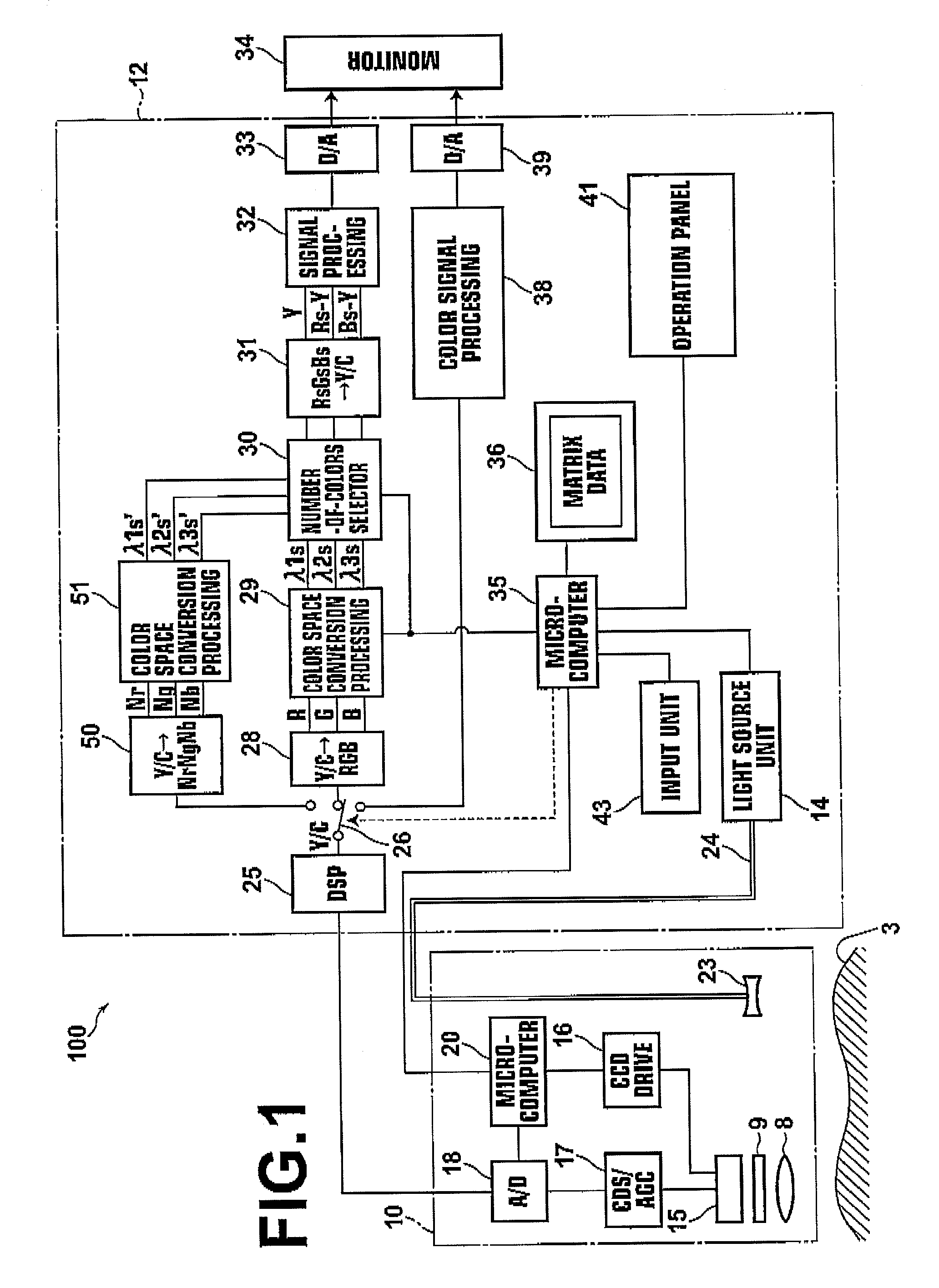
[0040]Hereinafter, embodiments of the present invention will be described in detail with reference to the attached drawings. FIG. 1 is a block diagram illustrating an electronic endoscope apparatus 100, as an imaging apparatus according to the present invention. The electronic endoscope apparatus 100 according to the present embodiment operates in an ordinary image mode and in a spectral image mode. In the ordinary image mode, an ordinary image of an observation target is formed. In the spectral image mode, a spectral image of the observation target is displayed. The spectral image is obtained by performing operation processing that will be described later. Further, under the spectral image mode, the electronic endoscope apparatus 100 operates in a visible spectral image mode and in a near-infrared spectral image mode. In the visible spectral image mode, a spectral image in a visible light region is formed based on image signals (R, G and B signals) of three colors in the visible li...

second embodiment

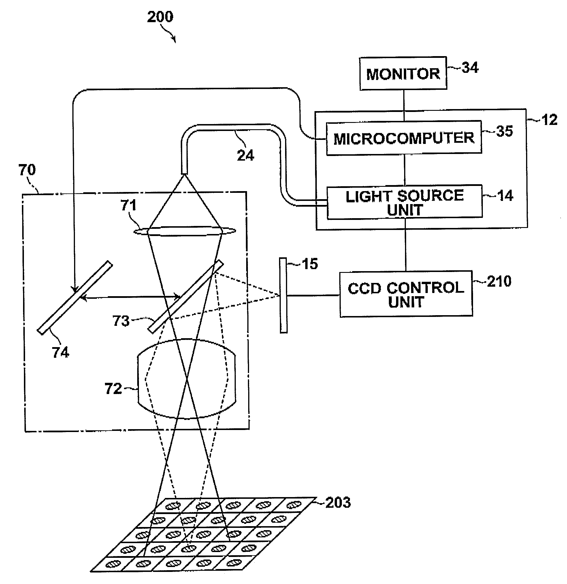
[0122]Further, the examination apparatus 200 in the second embodiment forms the ordinary image, the spectral image in the visible light region and the spectral image in the near-infrared region. However, for example, if it is not necessary to form the original image and a user wishes to perform only detection of fluorescence, the examination apparatus 200 may have a simpler structure. Next, this example will be described as a modification example of the examination apparatus 200 in comparison with the examination apparatus 200.

[0123]In the modification example, it is not necessary to form the ordinary image. Therefore, the white light source unit may be omitted from the light source unit 14. Further, the half mirror 7 may be omitted. Further, as the color filter that is provided on the light receiving surface of the CCD sensor 15, a single-peak filter that does not have a transmission characteristic of R, G and B but only have a transmission characteristic of Nr, Ng and Nb may be us...


PUM

PropertyMeasurementUnit
wavelengthaaaaaaaaaa
wavelength rangesaaaaaaaaaa

Abstract

An imaging apparatus includes a light source unit that selectively outputs white light and light in a different wavelength band to an observation target, an imaging unit including an imaging device, and a spectral image formation circuit that generates a spectral image signal for a specified wavelength by an operation using an image signal based on an output from the imaging unit and predetermined matrix data. The imaging unit selectively obtains an image of the observation target for each of first, second and third light components in a visible light region and an image for each of at least fourth and fifth light components in a near-infrared region. Further, the imaging unit includes first spectral devices that make only the first and fourth light components enter first pixels of the imaging device and second spectral devices that make only the second and fifth light components enter second pixels thereof.

Description

BACKGROUND OF THE INVENTION[0001]1. Field of the Invention[0002]The present invention relates to an imaging apparatus, and more specifically to an imaging apparatus that forms a spectral image (spectroscopic image) in a predetermined wavelength range (band) by performing operation processing on an image signal that is obtained by imaging an object to be observed (an observation target) that is illuminated with light.[0003]2. Description of the Related Art[0004]In recent years, in the field of imaging apparatuses, such as electronic endoscopes using solid-state imaging devices, imaging apparatuses that perform spectral imaging (spectroscopoic imaging) by using narrow band-pass filters in combination have drawn attention. These imaging apparatuses (Narrow Band Imaging—NBI) have built-in narrow band-pass filters and the combination of the narrow band-pass filters is determined based on the spectral reflectance at digestive organs (gastric mucosa or the like). The imaging apparatus incl...

Claims


Application Information

Patent Timeline
Patent Type & Authority Applications(United States)
IPC IPC(8): G01N21/25
CPCA61B1/00163A61B1/0669G01J3/36G01J3/51G01J3/513H04N5/2256H04N5/33H04N9/045H04N9/07H04N9/09H04N2209/043H04N2209/044H04N2209/045A61B1/00186A61B1/043A61B1/063A61B1/0638H04N23/56H04N23/125H04N23/13H04N23/12H04N25/134H04N23/20
Inventor TSUJITA, KAZUHIROSUNAGAWA, HIROSHIKIKUCHI, KATSUYAKAWANISHI, TETSUYA
Owner FUJIFILM CORP
Learn More