Jaw roll joint

a roll joint and jaw technology, applied in the field of jaw joint, can solve the problems of limiting the range of motion and frustrating the positioning of the end effector

Active Publication Date: 2013-03-19
TYCO HEALTHCARE GRP LP
View PDF18 Cites 1047 Cited by
  • Summary
  • Abstract
  • Description
  • Claims
  • Application Information

AI Technical Summary

Problems solved by technology

However, this type of rotation may frustrate the positioning of the end effector.
In some instances, the conductor may become entangled or may limit the range of motion achievable by the end effector.

Method used


Image

  • Jaw roll joint
  • Jaw roll joint
  • Jaw roll joint

Examples


Embodiment Construction

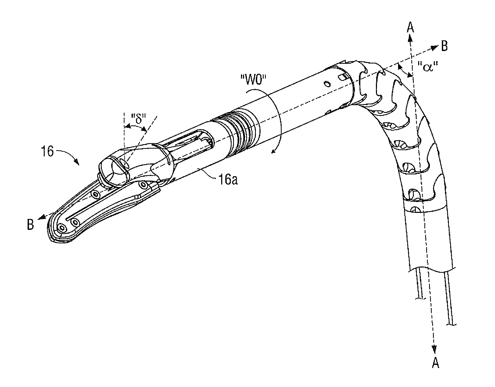
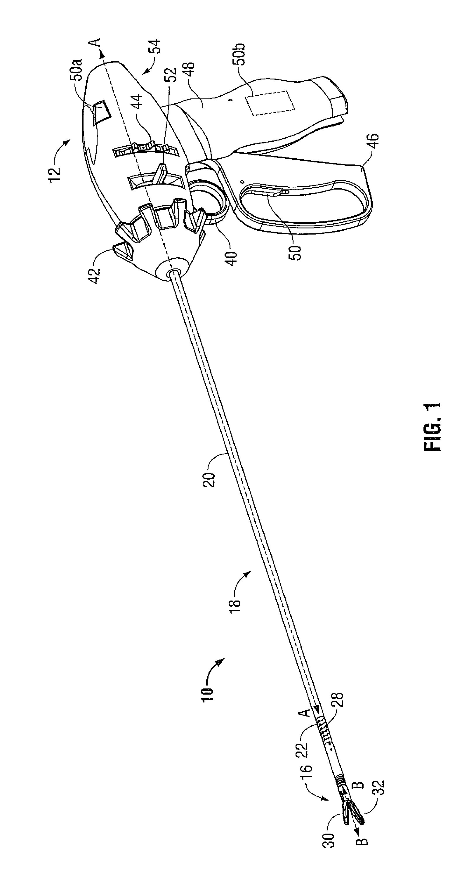
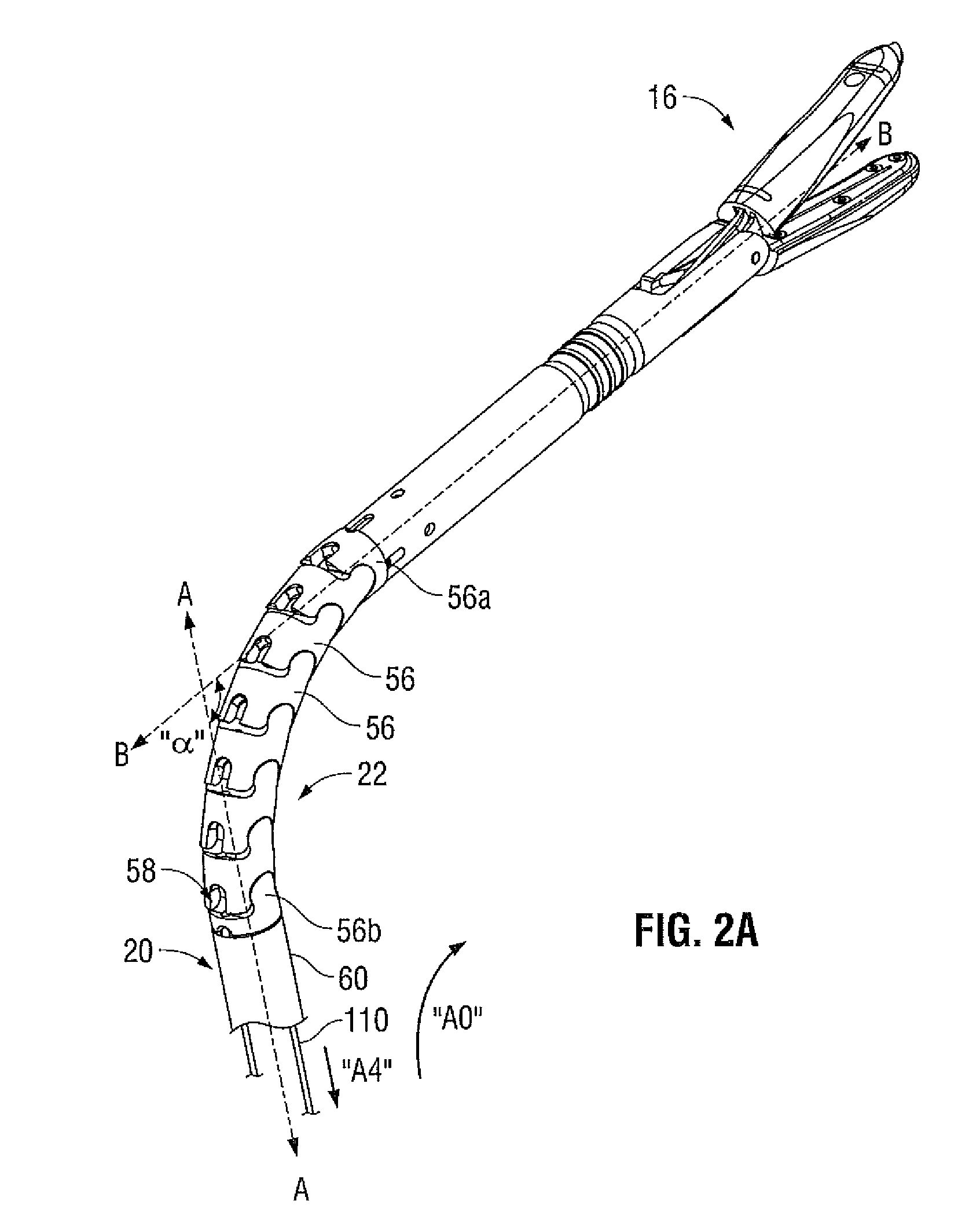
[0034]Referring initially to FIG. 1, a steerable endoscopic instrument is depicted generally as instrument 10. Instrument 10 includes a handle 12 near a proximal end, an end effector 16 near a distal end and an elongated shaft 18 therebetween. Elongated shaft 18 includes a proximal portion 20 extending from the handle 12 and an articulating distal portion 22 supporting the end effector 16. The proximal portion 20 defines a longitudinal axis A-A, and is sufficiently long to position the end effector 16 through a cannula (not shown). At least one joint 28 is established between the proximal and distal portions 20, 22 of the elongated shaft 18 permitting the distal portion 22 and the end effector 16 to articulate or pivot relative to the longitudinal axis A-A as described in greater detail below (see FIG. 2A). The end effector 16 defines an end effector axis B-B, which is aligned with the longitudinal axis A-A when the articulating distal portion 22 of the elongated shaft 18 is in a “h...


PUM


Abstract

A surgical instrument includes a handle, and an elongated shaft extending from the handle. An end effector extending from the elongated shaft is in communication with a source of electrosurgical energy and defines an end effector axis. A roll joint couples the end effector to the elongated shaft and includes a first tubular structure extending distally from the elongated shaft and a second tubular structure rotatably coupled to the first tubular structure. The second tubular structure supports the end effector such that the end effector is rotatable about the end effector axis. A cable wrap volume may be disposed within one of the first and second tubular structures, and a conductor for supplying the end effector with electrosurgical energy is coiled about the end effector axis within the cable wrap volume such that rotation of the end effector about the end effector axis in a first direction unwinds the conductor.

Description

BACKGROUND[0001]1. Technical Field[0002]The present disclosure relates to a surgical apparatus having an elongated shaft for laparoscopic and endoscopic procedures. In particular, the disclosure relates to a surgical apparatus having a roll joint permitting an end effector to rotate relative to a distal portion of the elongated shaft.[0003]2. Background of Related Art[0004]Typically in a laparoscopic, an endoscopic, or other minimally invasive surgical procedure, a small incision or puncture is made in a patient's body. A cannula is then inserted into a body cavity through the incision, which provides a passageway for inserting various surgical devices such as scissors, dissectors, retractors, or similar instruments. To facilitate operability through the cannula, instruments adapted for laparoscopic surgery typically include a relatively narrow shaft supporting an end effector at its distal end and a handle at its proximal end. Arranging the shaft of such an instrument through the c...

Claims


Application Information

Patent Timeline
Patent Type & Authority Patents(United States)
IPC IPC(8): A61B18/14
CPCA61B17/29A61B18/1445A61B2019/2242A61B18/14A61B2017/003A61B2017/00323A61B2017/00477A61B2017/2905A61B2017/2927A61B2017/293A61B2018/00178A61B2018/00601A61B2018/0063A61B2018/1412A61B2018/1455A61B2018/1861A61B17/320016A61B34/71A61B18/1492
Inventor MUELLER, PETER M.
Owner TYCO HEALTHCARE GRP LP
Why Eureka
Try Eureka