Analog television receiver for processing intermediate frequency TV signal

a technology for tv signals and analog televisions, applied in the field of analog television, can solve the problems of serious affecting the quality of tv signals, unsatisfactory analog demodulation effects, etc., and achieve the effect of increasing demodulation efficiency

Active Publication Date: 2013-03-26
XUESHAN TECH INC
View PDF4 Cites 0 Cited by
  • Summary
  • Abstract
  • Description
  • Claims
  • Application Information

AI Technical Summary

Benefits of technology

[0004]In view of the foregoing issues, one object of the present invention is to provide an analog TV receiver capable of converting a received analog TV signal to a digital TV signal and performing digital demodulation thereby increasing demodulation efficiency.

Problems solved by technology

However, the effect of analog demodulation is not always ideal, and may seriously affect quality of a TV signal.

Method used


Image

  • Analog television receiver for processing intermediate frequency TV signal
  • Analog television receiver for processing intermediate frequency TV signal
  • Analog television receiver for processing intermediate frequency TV signal

Examples


first embodiment

[0019]In the first embodiment, the SAW filtering circuit 22 respectively filters out and transmits the video part and the audio part of the analog IF TV signal to the IF circuit 23 for processing as illustrated in FIG. 4. The SAW filtering circuit 22 comprises a video filter 221, for filtering out an analog IF video signal from the analog IF TV signal; and an audio filter 222, for filtering out an analog IF audio signal from the analog IF TV signal. The PGA 31 comprises PGA units 311 and 312, and the ADC 32 comprises ADC units 321 and 322. The PGA unit 311 and the ADC unit 321 form a video signal path for converting the analog IF video signal to a digital IF video signal. The PGA unit 312 and the ADC unit 322 form an audio signal path for converting the analog IF audio signal to a digital IF audio signal. Accordingly, cross talk between the video signal path and the audio signal path is reduced by separating signal paths of the video part and the audio part. The digital TV signal ou...

second embodiment

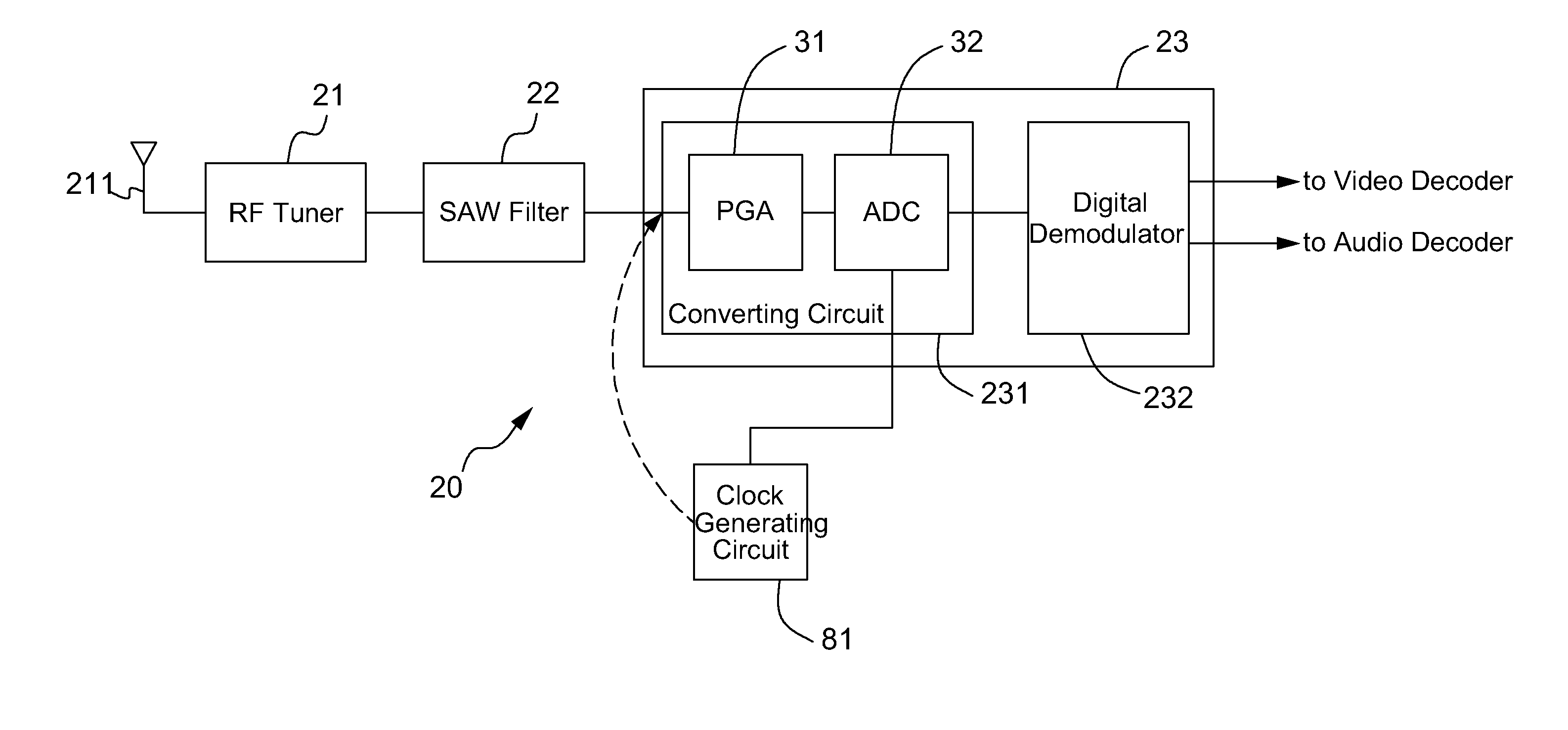
[0024]Influences of the oscillation frequency mean that, harmonics of an oscillation frequency (for synthesizing a desired sampling clock signal of the ADCs 32 and 52) adopted by the analog TV receiver 20 directly lie within the IF signal bandwidth, or are overlapped with the IF signal bandwidth during sampling due to self-aliasing, thereby undesirably affecting TV signal quality. FIG. 8A is a schematic diagram of a clock generating circuit and the analog TV receiver illustrated in FIG. 3 in accordance with an embodiment of the present invention. A clock generating circuit 81 generates a sampling clock signal according to an oscillation frequency, and transmits the sampling clock signal to the ADC 32. The clock generating circuit 81 comprises an oscillator and a frequency synthesizer (not shown). The oscillator generates an oscillation clock signal, and the frequency synthesizer synthesizes the sampling clock signal according to the oscillation clock signal. Since the oscillation cl...


PUM


Abstract

An analog television (TV) receiver converts a received analog TV signal to a digital TV signal and performs digital demodulation to increase demodulation efficiency. The analog TV receiver includes a radio frequency (RF) turner and an intermediate frequency (IF) circuit. The RF tuner converts the received analog RF TV signal to an analog IF TV signal. The IF circuit includes a converting circuit and a digital demodulator. The converting circuit converts the analog IF TV signal to a digital TV signal. The digital demodulator demodulates the digital TV signal to generate a digital demodulated video signal and a digital demodulated audio signal.

Description

CROSS REFERENCE TO RELATED PATENT APPLICATION[0001]This patent application is based on Taiwan, R.O.C. patent application No. 99137577 filed on Nov. 2, 2010.FIELD OF THE INVENTION[0002]The present invention relates to an analog television (TV), and more particularly, to an analog TV receiver.BACKGROUND OF THE INVENTION[0003]A receiver is a crucial component in an analog TV system and environment. In the prior art, a receiver of an analog TV performs signal demodulation via an analog approach, and a typical hardware structure as illustrated in FIG. 1. An analog TV receiver 10 comprises a radio frequency (RF) tuner 11, a surface audio wave (SAW) filtering circuit 12, a programmable gain amplifier (PGA) 13, an analog demodulator 14, and analog-to-digital converters (ADCs) 15 and 16 for sending signals to other components, such as decoders. The RF tuner 11 converts an analog RF TV signal received by an antenna 111 to an analog IF TV signal. The SAW filtering circuit 12 filters out noises...

Claims


Application Information

Patent Timeline
Patent Type & Authority Patents(United States)
IPC IPC(8): H04N5/455H03M1/12
CPCH04N21/4382H04N5/455
Inventor WANG, FUCHENG
Owner XUESHAN TECH INC
Why Eureka
Try Eureka