A wavelength demodulation method and system

A wavelength demodulation and wavelength technology, which is applied in the direction of using optical devices to transmit sensing components, etc., can solve the problems of inability to achieve multi-wavelength simultaneous output, unsuitable for general engineering occasions, high cost of laser source devices, etc., to achieve cost-effective wavelength demodulation , low-cost wavelength demodulation, and the effect of improving demodulation efficiency

Active Publication Date: 2017-05-31
INFORMATION & COMMNUNICATION BRANCH STATE GRID JIANGXI ELECTRIC POWER CO +2
View PDF6 Cites 0 Cited by
  • Summary
  • Abstract
  • Description
  • Claims
  • Application Information

AI Technical Summary

Problems solved by technology

[0003] The current wavelength demodulation method generally can only detect one specific wavelength information at a time, and cannot realize simultaneous output of multiple wavelengths, so it takes a long time. In addition, in the existing wavelength demodulation method, the cost of the laser source device used is also high , making it unsuitable for general engineering occasions

Method used


Image

  • A wavelength demodulation method and system
  • A wavelength demodulation method and system
  • A wavelength demodulation method and system

Examples


Embodiment 1

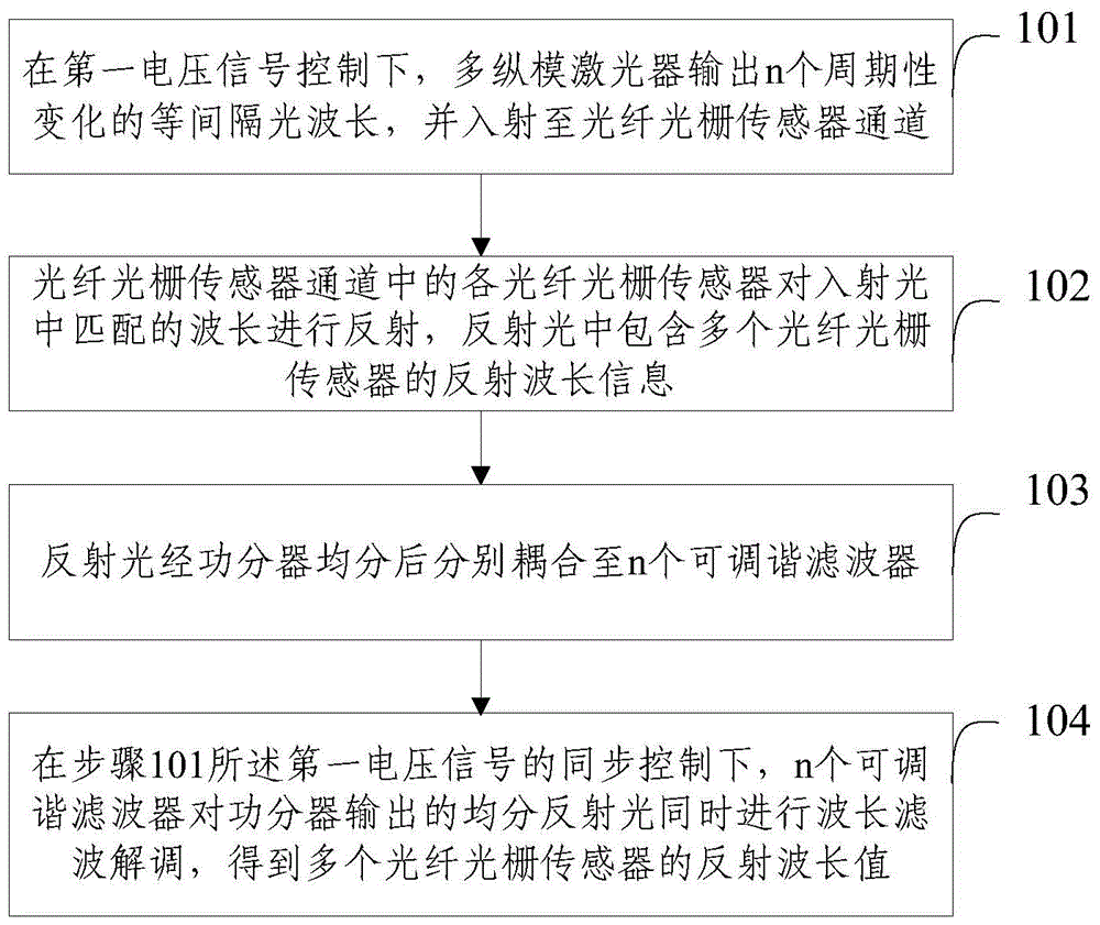
[0037] Embodiment 1 of the present invention proposes a wavelength demodulation method, see figure 1 , including the following steps:

[0038] Step 101: Under the control of the first voltage signal, the multi-longitudinal-mode laser outputs n periodically changing light wavelengths at equal intervals, and injects them into the channel of the fiber grating sensor.

[0039] In this step, under the control of the first voltage signal, the multi-longitudinal mode laser outputs n periodically changing optical wavelengths at equal intervals, simulating the output of continuous wavelength optical signals in a specific wavelength range, and injecting them into the fiber grating sensor channel; , the multi-longitudinal mode laser outputs n periodically varying light wavelengths at equal intervals, and the changing range of one light wavelength is seamlessly adjacent to the changing range of adjacent light wavelengths. In addition, the first voltage signal is a periodically changing v...

Embodiment 2

[0052] Embodiments of the present invention also propose a wavelength demodulation system, see Figure 4 , the system consists of:

[0053] An optical wavelength output module 401, configured to output n periodically changing equally spaced optical wavelengths from the multi-longitudinal mode laser under the control of the first voltage signal, and inject them into the fiber grating sensor channel;

[0054] The fiber grating sensor module 402 is used for each fiber grating sensor in the fiber grating sensor channel to reflect the matched wavelength in the incident light, and the reflected light includes wavelength information of multiple fiber grating sensors;

[0055] An optical power splitting module 403, the reflected light is distributed by the power splitter and coupled to n tunable filters respectively;

[0056] The demodulation module 404 is configured to, under the synchronous control of the first voltage signal described in the optical wavelength output module 401, n...

Embodiment 3

[0063] The working process of the wavelength demodulation system of the present invention will be described in more detail below through a specific example. see Figure 5 , the system consists of:

[0064] Control unit 1 , F-P cavity multi-longitudinal mode laser 2 , beam splitter 3 , fiber grating sensor 4 , power splitter 5 , tunable filter 6 , photodetector 7 and data processing unit 8 .

[0065] Wherein, the control unit 1 sends a periodically changing voltage signal to synchronously control the change of the wavelength of the multi-longitudinal mode laser and the filtering wavelength of the tunable filter.

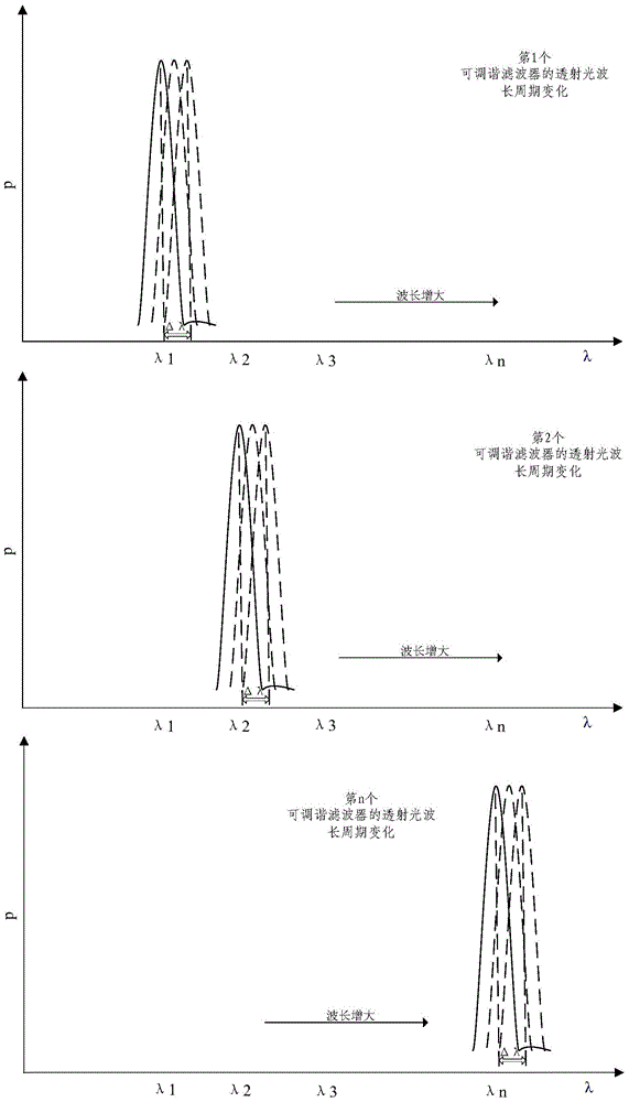
[0066] The F-P cavity multi-longitudinal mode laser 2 outputs n periodically changing equally spaced light wavelengths, and the change range of one light wavelength is seamlessly adjacent to the change range of adjacent light wavelengths, as shown in Figure 4 shown.

[0067] The output of n periodically changing light wavelengths at equal intervals is incident on ...


PUM


Abstract

The invention provides a wavelength demodulation method, the method comprising: S1. Under the control of the first voltage signal, the multi-longitudinal mode laser outputs n periodically changing light wavelengths at equal intervals, and is incident on the fiber grating sensor channel; S2 . Each FBG sensor in the FBG sensor channel reflects the matched wavelength in the incident light, and the reflected light contains the reflected wavelength information of multiple FBG sensors; S3. The reflected light is divided into n tunable filters; S4. Under the synchronous control of the first voltage signal described in S1, n tunable filters simultaneously perform wavelength filtering and demodulation on the evenly divided reflected light output by the power divider to obtain a plurality of fiber grating sensors reflection wavelength value. The invention can realize synchronous demodulation of multiple wavelengths.

Description

technical field [0001] The invention relates to the technical field of optical fiber sensing, in particular to a wavelength demodulation method and system. Background technique [0002] In recent years, research on optical fiber sensing technology based on wavelength modulation / demodulation has progressed rapidly, and has been widely used in civil engineering, petroleum, electric power, transportation and other fields, and has become the mainstream technology of optical fiber sensors. The key technology in the FBG sensing system is the detection of FBG wavelength information. [0003] The current wavelength demodulation method generally can only detect one specific wavelength information at a time, and cannot realize simultaneous output of multiple wavelengths, so it takes a long time. In addition, in the existing wavelength demodulation method, the cost of the laser source device used is also high. , making it unsuitable for general engineering occasions. Contents of the...

Claims


Application Information

Patent Timeline
Patent Type & Authority Patents(China)
IPC IPC(8): G01D5/26
Inventor 李路明张治国李星谕孙艳飞刘赐麟刘志明胡彬
Owner INFORMATION & COMMNUNICATION BRANCH STATE GRID JIANGXI ELECTRIC POWER CO
Why Eureka
Try Eureka