Object detection in depth images

a technology of object detection and depth image, which is applied in the field of object detection in depth image, can solve the problems of not being applicable to some surveillance applications, affecting the efficiency of the method, and affecting the accuracy of the detection method, so as to avoid the calculation of the size of the detection window during the object detection, avoid the effect of classifier scanning and improved method efficiency

Active Publication Date: 2013-03-26
MITSUBISHI ELECTRIC RES LAB INC
View PDF21 Cites 33 Cited by
  • Summary
  • Abstract
  • Description
  • Claims
  • Application Information

AI Technical Summary

Benefits of technology

[0010]One advantage of the depth image is that the acquisition of the depth image may not require light. The depth image can be produced by a depth sensor, which, for each pixel in the depth image, determines an estimate of the distance from a depth sensor to a point in a scene corresponding to the pixel. There are various technologies that are used to construct depth sensors, and most of technologies do not require light. This gives depth sensors an advantage over regular video cameras for surveillance applications. However, a usage of depth sensors creates a need for new object detection method that can take advantage of the depth values at each pixel in the depth image.
[0011]Some embodiments of current invention are based on a realization that an approximate size of the object of a class in the depth image can be determined based on a size of a typical object of the class and the depth values of the pixels. Thus, for any pixel, a size of the detection window can be determined, and the classifier need only be applied to the detection window around the pixel. Accordingly, the scanning of the classifier can be avoided, and so that the efficiency of the method is improved.
[0012]The size of the detection window, as a function of a depth value, can be predetermined or computed during an operation of the depth sensor. For example, various sizes of the detection window can be stored in a lookup value, and can be retrieved from the lookup table using the depth values as keys. Accordingly, a calculation of the size of the detection window during the object detection can be avoided, and the efficiency of the object detection can be improved. Also, the sizes of the detection windows can be determined for various poses of the object corresponding to the poses used for training the classifier. Also, the sizes of the detection window can be determined based on a resolution of the depth sensor, and can be reused for different applications.
[0013]Furthermore, a segmentation of a foreground region within the detection window can be determined based on the depth value of the pixel within the detection object and the size of the object, e.g., a depth of the object. Thus, the detection of the object can be performed for this foreground region, which can be normalized to improve the efficiency and accuracy of the classifier. In addition, the segmentation using depth values yields a rough silhouette that can be used to compute a feature vector.
[0014]Moreover, if a number of pixels in the foreground region is less than a threshold, the foreground region can be classified as not including the object. Thus, the classifier can be applied only to “promising” regions, which further improve the efficiency of the method. Also, the classifier can be trained only for one training size of an input image to the classifier. The detection window and / or the foreground region can be resized to the training size of the classifier for the object detection.
[0015]Furthermore, when the depth image is part of a time sequence of depth images, e.g. a depth video, the depth values of the pixels in the foreground region can be modified with depth values of corresponding pixels from a temporally adjacent depth image. For example, for each detection window, a temporal volume of depth data can be determined and the feature vector can be computed based on the depth data, which can further improve reliability of the object detection.

Problems solved by technology

However, conventional object detection methods have a number of problems.
Most methods for detecting objects work on visible light images or video and do not work at night without providing artificial light sources.
However, such solutions can be expensive, and are not applicable for some surveillance applications.
However the scanning window approach is computationally complex.

Method used


Image

  • Object detection in depth images
  • Object detection in depth images
  • Object detection in depth images

Examples


Embodiment Construction

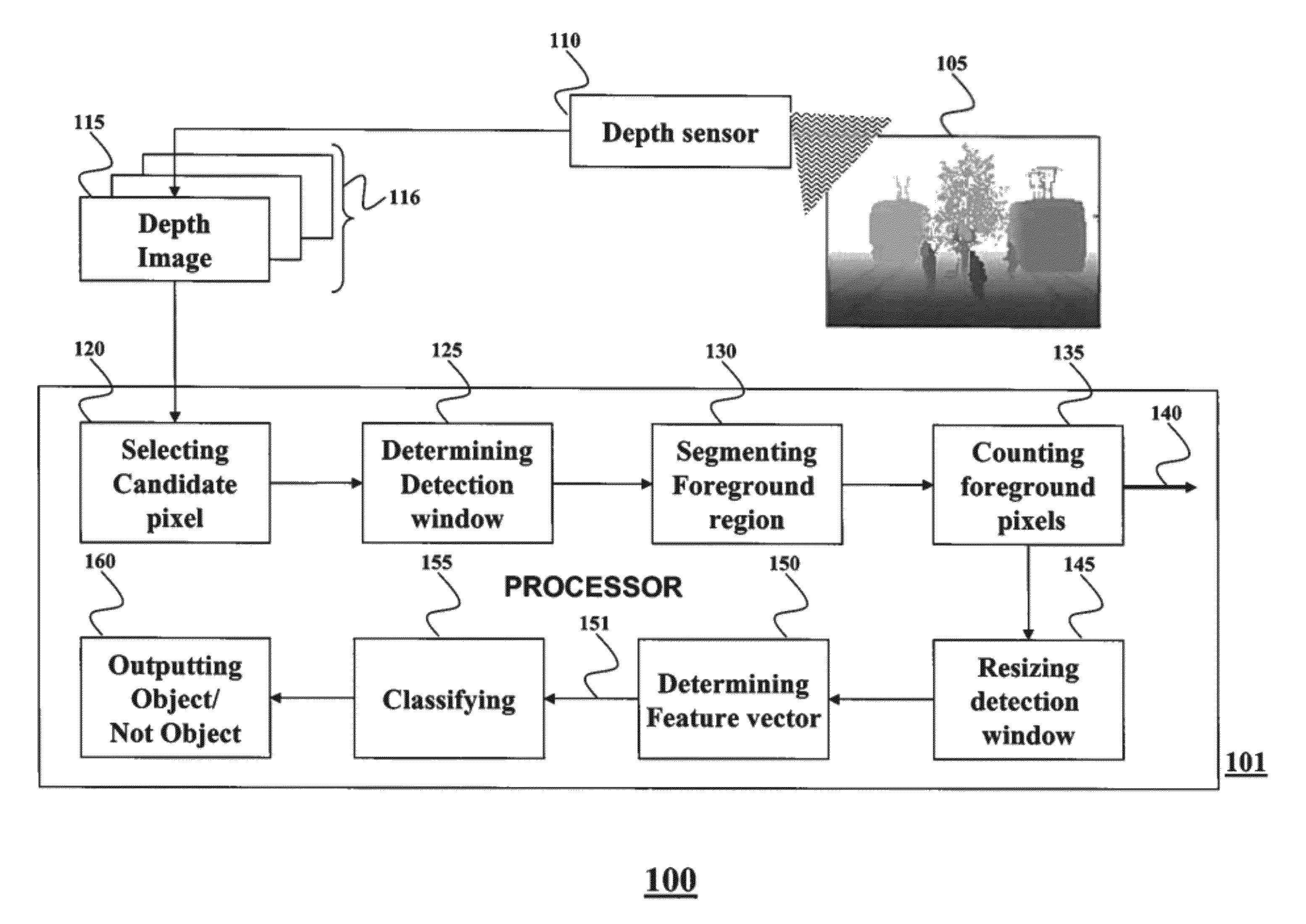
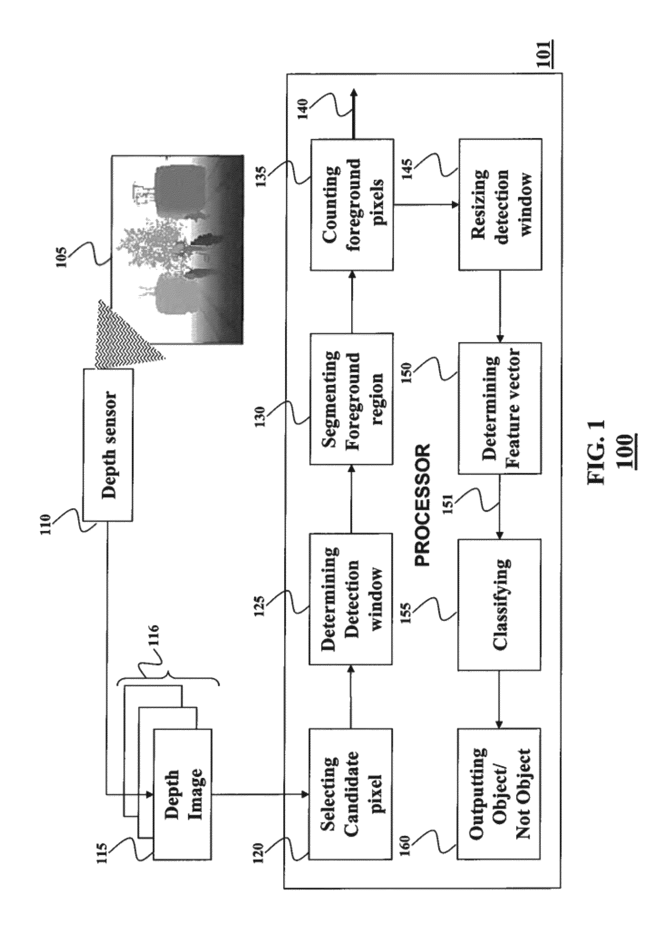
[0024]FIG. 1 shows a block diagram of a method 100 for detecting an object in a depth image 115. The depth image of a scene 105 can be acquired by a depth sensor 110. The depth sensor can be any type of sensors configured to produce the depth image, such that each pixel in the depth image has a depth value indicative of a distance between the depth sensor and a corresponding object in the scene.

[0025]For example, light such as infrared (IR) light can be irradiated on an object, and a time of flight (TOF) is measured by sensing reflected light to measure a distance (depth value) from a depth sensor to each part of the object. The depth image 116 can be part of a time sequence of the depth images 116, e.g. a depth video. The method 100 can be implemented using a processor 101.

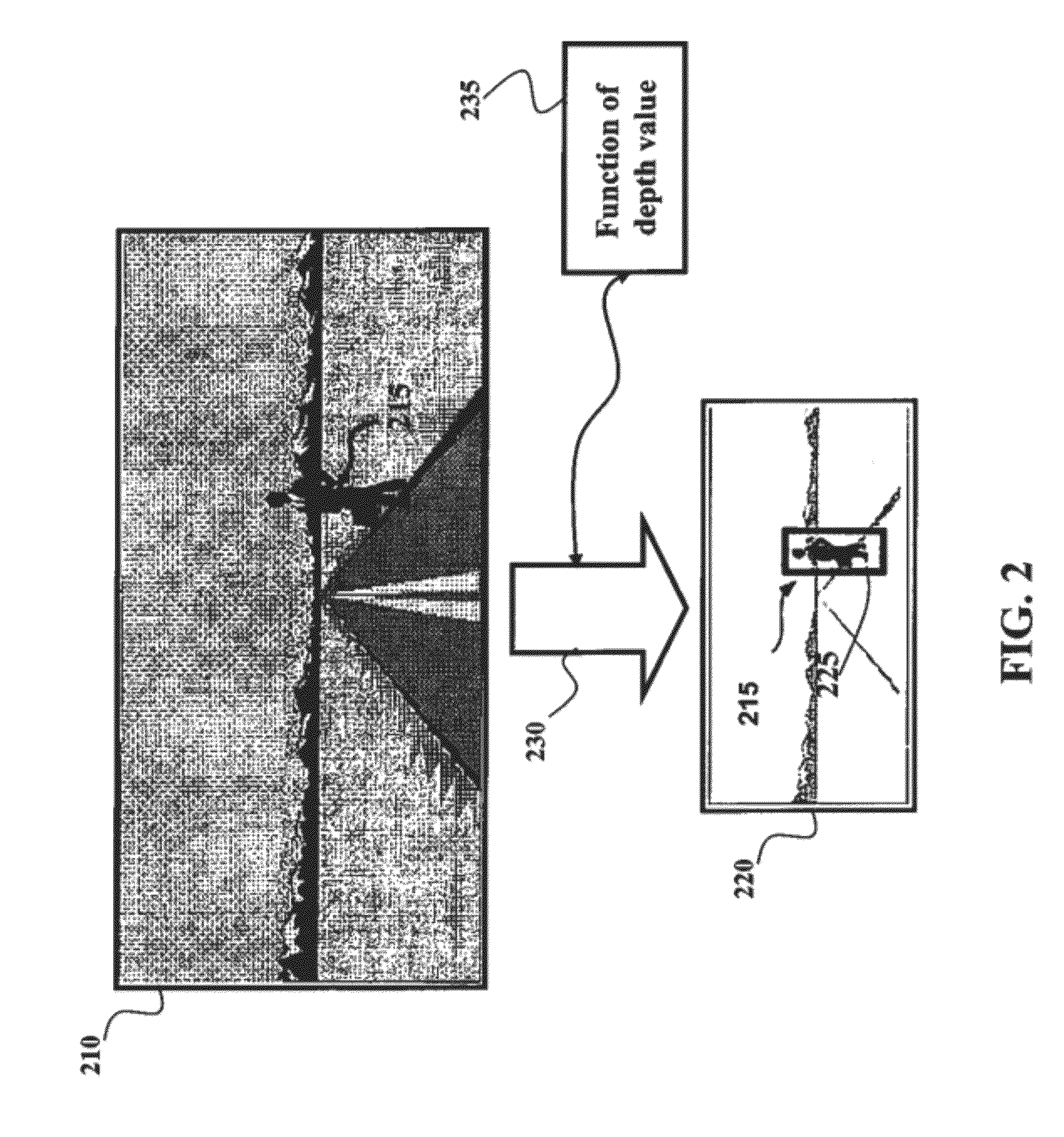
[0026]As shown in FIG. 2, the object to be detected in the depth image belongs to a specific class of objects, e.g., people, or cars. Some embodiments of the invention are based on a realization that for each can...


PUM


Abstract

A method for detecting an object in a depth image includes determining a detection window covering a region in the depth image, wherein a location of the detection window is based on a location of a candidate pixel in the depth image, wherein a size of the detection window is based on a depth value of the candidate pixel and a size of the object. A foreground region in the detection window is segmented based on the depth value of the candidate pixel and the size of the object. A feature vector is determined based on depth values of the pixels in the foreground region and the feature vector is classified to detect the object.

Description

FIELD OF THE INVENTION[0001]This invention relates generally to detecting an object in an image, and more particularly to detecting the object in a depth image.BACKGROUND OF THE INVENTION[0002]Object detection is related to computer vision and image processing applications that deals with detecting instances of semantic objects of a certain class (such as humans, buildings or cars) in digital images and videos. Object detection has applications in many areas of computer vision, including image retrieval, and video surveillance. However, conventional object detection methods have a number of problems.[0003]For example, a major shortcoming of most conventional surveillance systems is a reliance on visible light cameras. Most methods for detecting objects work on visible light images or video and do not work at night without providing artificial light sources. However, such solutions can be expensive, and are not applicable for some surveillance applications.[0004]Also, conventional me...

Claims


Application Information

Patent Timeline
Patent Type & Authority Patents(United States)
IPC IPC(8): G06K9/00G06K9/34
CPCG06K9/00201G06V20/64
Inventor JONES, MICHAEL J.TUZEL, ONCELSI, WEIGUANG
Owner MITSUBISHI ELECTRIC RES LAB INC
Why Eureka
Try Eureka