Heat exchanger assembly

a technology of heat exchangers and components, applied in the direction of indirect heat exchangers, stationary conduit assemblies, lighting and heating apparatus, etc., can solve the problems of increasing refrigerant pressure differences and affecting heat exchanger performance, and achieve the effect of reducing the temperature value rang

Inactive Publication Date: 2013-04-02
MAHLE INT GMBH
View PDF15 Cites 6 Cited by
  • Summary
  • Abstract
  • Description
  • Claims
  • Application Information

AI Technical Summary

Problems solved by technology

This increases a refrigerant pressure difference between the inlet header 22 and outlet header 24, which is also usually detrimental to heat exchanger performance.

Method used


Image

  • Heat exchanger assembly
  • Heat exchanger assembly
  • Heat exchanger assembly

Examples


Embodiment Construction

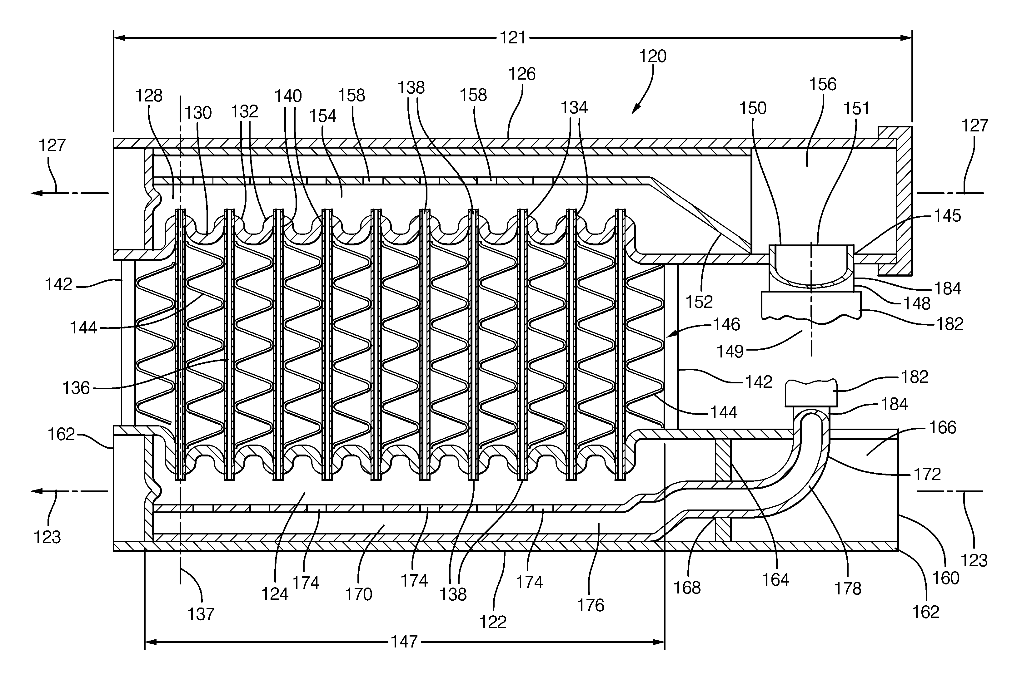
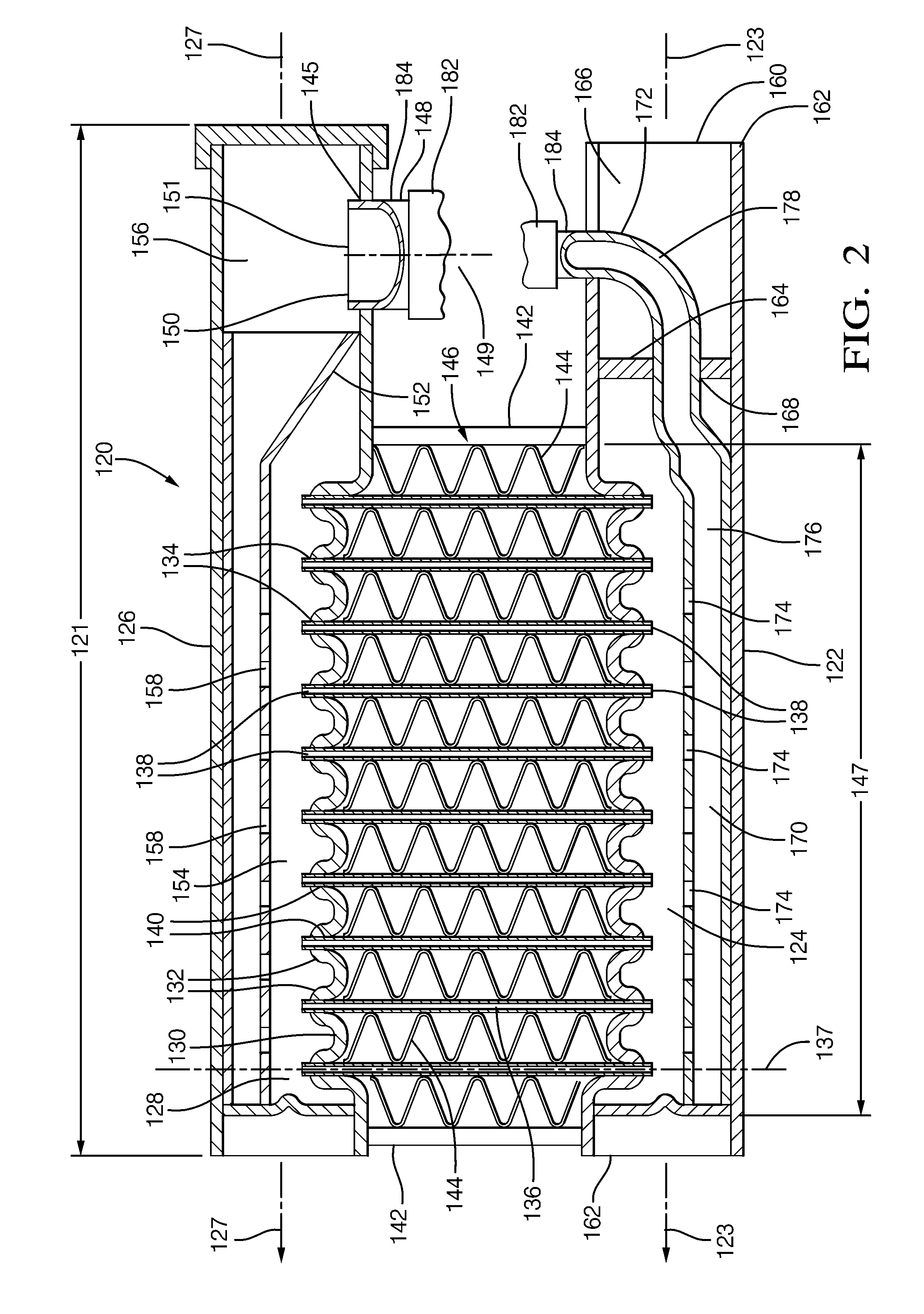
[0024]In accordance with an embodiment, FIG. 2 illustrates a heat exchanger assembly 120 comprising an inlet header 122 defining an inlet cavity 124 extending along an inlet header axis 123. An outlet header 126 defines an outlet cavity 128 extending along an outlet header axis 127. The inlet header axis 123 is substantially parallel to the outlet header axis 127. As used herein, substantially parallel typically means within ±15° of absolutely parallel. The inlet header 122 is for receiving a refrigerant for liquid to vapor transformation and the outlet header 126 is for collecting refrigerant vapor. A heat exchanger with this configuration is commonly known as an evaporator. Alternate embodiments can be envisioned where the header 126 is for receiving a refrigerant vapor for vapor to liquid transformation and the header 122 is for collecting refrigerant liquid. A heat exchanger with this configuration is commonly known as a condenser.

[0025]Each header 122, 126 includes a lanced sur...


PUM


Abstract

A heat exchanger assembly that includes an outlet header / manifold defining an outlet cavity, an outlet tube in fluidic communication with the outlet cavity, and a heat exchanger core. The outlet tube and the outlet cavity cooperate to reduce a temperature value range across the heat exchanger core by equalizing refrigerant distribution between the refrigerant tubes within the heat exchanger core. The length of the heat exchanger headers / manifolds may be increased for a predetermined packaging width because the outlet tube and inlet conduit may exit the headers / manifolds perpendicularly rather than axially, allowing the heat exchanger core width to be increased. The increased heat exchanger core width allows additional refrigerant tubes to be included in the heat exchanger core, providing decreased air pressure difference for air flowing through the heat exchanger assembly and increased heat capacity of the heat exchanger assembly.

Description

[0001]The invention generally relates to heat exchanger assemblies, and more particularly relates to features in heat exchangers for reducing the range or a spread of temperature value range across the heat exchanger core.BACKGROUND OF INVENTION[0002]Due to their high performance, automotive style brazed heat exchangers are being developed for residential air conditioning applications. An example of such a heat exchanger is disclosed in US Patent Application Publication 2009 / 0173483 by Beamer et al., published Jul. 9, 2009. As shown in FIG. 1, automotive style heat exchangers typically have a pair of headers 22, 24 with a plurality of refrigerant tubes 26 defining fluid passages 28 to provide fluidic communication between the headers 22, 24. The refrigerant tubes 26 extend in a spaced and parallel relationship and are generally perpendicular to the header axes 23 and 25. A pair of core supports 30 are disposed outwards of the refrigerant tubes 26 and extend between the headers 22, 2...

Claims


Application Information

Patent Timeline
Patent Type & Authority Patents(United States)
IPC IPC(8): F28F9/02F28F9/04
CPCF28D1/05366F28F9/0246F28F9/0273F28F9/028F28F9/013F28F9/0263F28F13/06
Inventor POLISOTO, DAVID M.PAUTLER, DONALD R.WINTERSTEEN, DOUGLAS C.COOPER, JR., RICHARD V.SAMUELSON, DAVID E.
Owner MAHLE INT GMBH
Why Eureka
Try Eureka