
Printed circuit substrate and method of manufacturing the same

a technology of printed circuit substrate and manufacturing method, which is applied in the direction of printed circuit manufacturing, printed circuit aspects, conductive pattern formation, etc., can solve the problems of electrochemical instability, electrical short circuit, and degrade the reliability of printed circuit substrate, so as to prevent an electrical short circuit due, prevent electrochemical migration, and improve high-density and reliability

Active Publication Date: 2013-04-02
SAMSUNG ELECTRO MECHANICS CO LTD +1
View PDF10 Cites 0 Cited by
  • Summary
  • Abstract
  • Description
  • Claims
  • Application Information

AI Technical Summary

Benefits of technology

[0008]Therefore, the present invention is provided to solve the problems that may be generated from a printed circuit substrate and a method of manufacturing the same. More specifically, the present invention has been made in an effort to provide a printed circuit substrate that includes a barrier layer that is disposed on at least one surface of a circuit pattern and suppresses electrochemical migration from the circuit pattern, such that it can prevent an electrical short circuit due to electrochemical migration, thereby making it possible to improve high-density and reliability, and a method of manufacturing the same.
[0009]An object of the present invention is to provide a printed circuit substrate. The printed circuit substrate may include an insulating layer; and a circuit layer that includes a circuit pattern disposed on the insulating layer and a barrier layer that is disposed to cover at least one surface of the circuit pattern and suppresses electrochemical migration from the circuit pattern.
[0014]Another object of the present invention is to provide a method of manufacturing a printed circuit substrate. The method of manufacturing the printed circuit substrate may include: forming a circuit pattern on an insulating layer; and forming a barrier layer that suppresses electrochemical migration from the circuit pattern on at least one surface of the circuit pattern.

Problems solved by technology

When the printed circuit substrate is operated, in particular, while being exposed to high-temperature and high-humidity environment, electrochemical migration (hereinafter, referred to as ‘ECM’) phenomenon is generated, such that it may degrade reliability of the printed circuit substrate.
Herein, the electrochemical migration is a phenomenon that when voltage is applied between two metal electrodes that are electrically insulated, together with the absorption of moisture including pollutants, it becomes electrochemically unstable, such that conductive filaments grow between the two metal electrodes to cause an electrical short circuit.
Therefore, reliability of the printed circuit substrate becomes more problematic due to the ECM.

Method used


Image

  • Printed circuit substrate and method of manufacturing the same
  • Printed circuit substrate and method of manufacturing the same
  • Printed circuit substrate and method of manufacturing the same

Examples


first embodiment

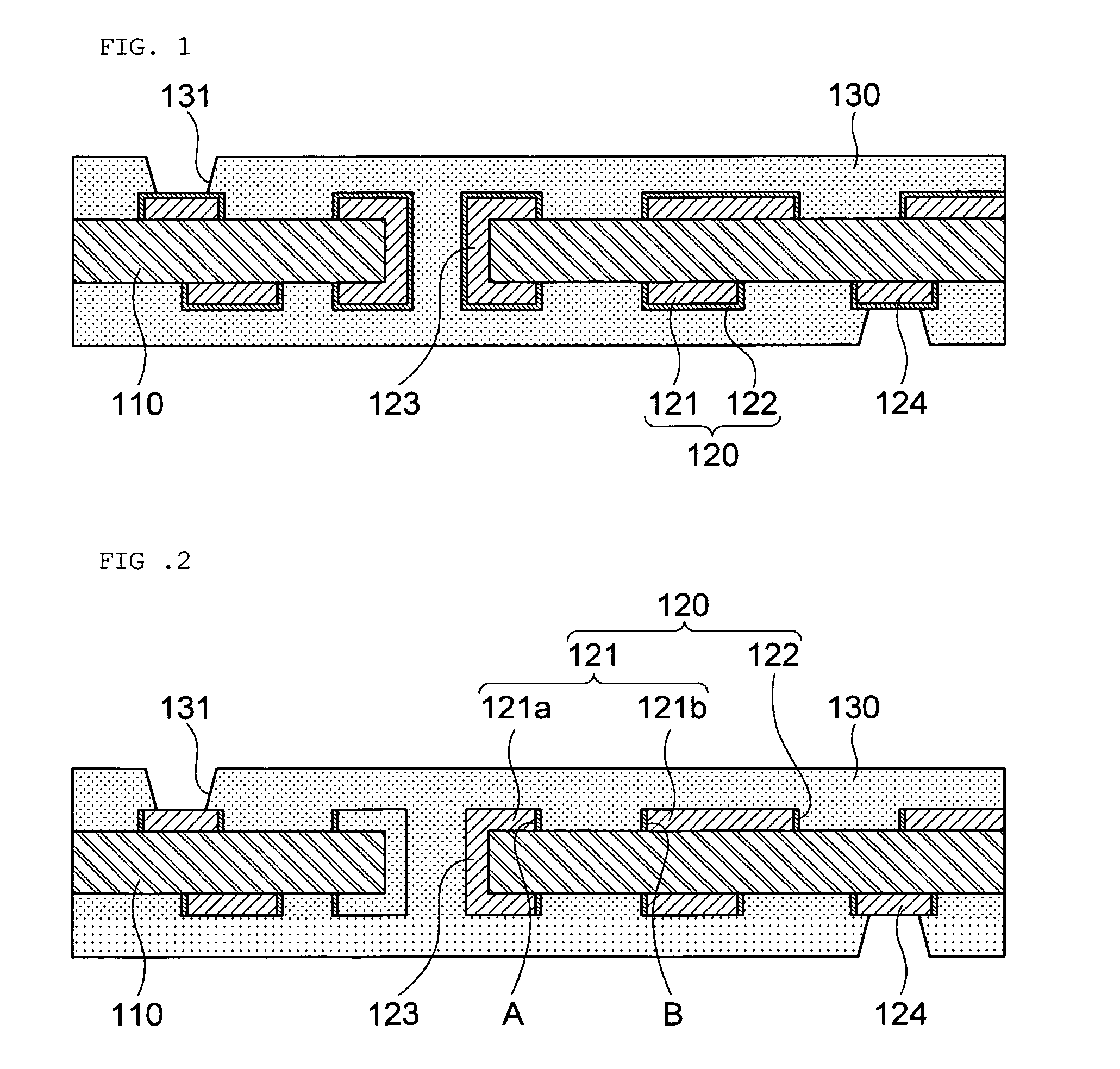
[0026]FIG. 1 is a cross-sectional view of a printed circuit substrate according to the present invention.

[0027]Referring to FIG. 1, the printed circuit substrate according to the first embodiment of the present invention may include a circuit layer 120 that is disposed on a first insulating layer 110.

[0028]The first insulating layer 110 may be made of an insulating resin or an insulating resin in which a glass fiber is impregnated. The insulating resin may be, for example, a polyimide based resin, an epoxy based resin, and the like. The insulating layer may have a form of a substrate or a film. However, the material and the form of the insulating layer are not limited in the embodiment of the present invention.

[0029]The circuit layer 120 may be disposed on the upper surface and lower surface of the first insulating layer 110, respectively, while forming an interlayer connection through a via 123. Herein, the circuit layer 120 may include circuit patterns 121 made of metal and a barr...

second embodiment

[0043]FIG. 2 is a cross-sectional view of a printed circuit substrate according to the present invention.

[0044]Referring to FIG. 2, the printed circuit substrate according to the second embodiment of the present invention may include a circuit layer 120 that is disposed on a first insulating layer 110. Herein, the circuit layer 120 may include a circuit pattern 121 and a barrier layer 122 that is disposed on one surface of the circuit pattern 121.

[0045]More specifically, the circuit pattern 121 may include first and second circuit patterns 121a and 121b that are adjacent to each other. Herein, the barrier layers 122 may be disposed on the first side surface A of the first circuit pattern 121a and the second side surface B of the second circuit pattern 121b that are opposite to each other, respectively. However, the embodiment of the present invention is not limited thereto and thus, the barrier layer 122 may also be disposed on only any one of the first and second side surfaces A an...

third embodiment

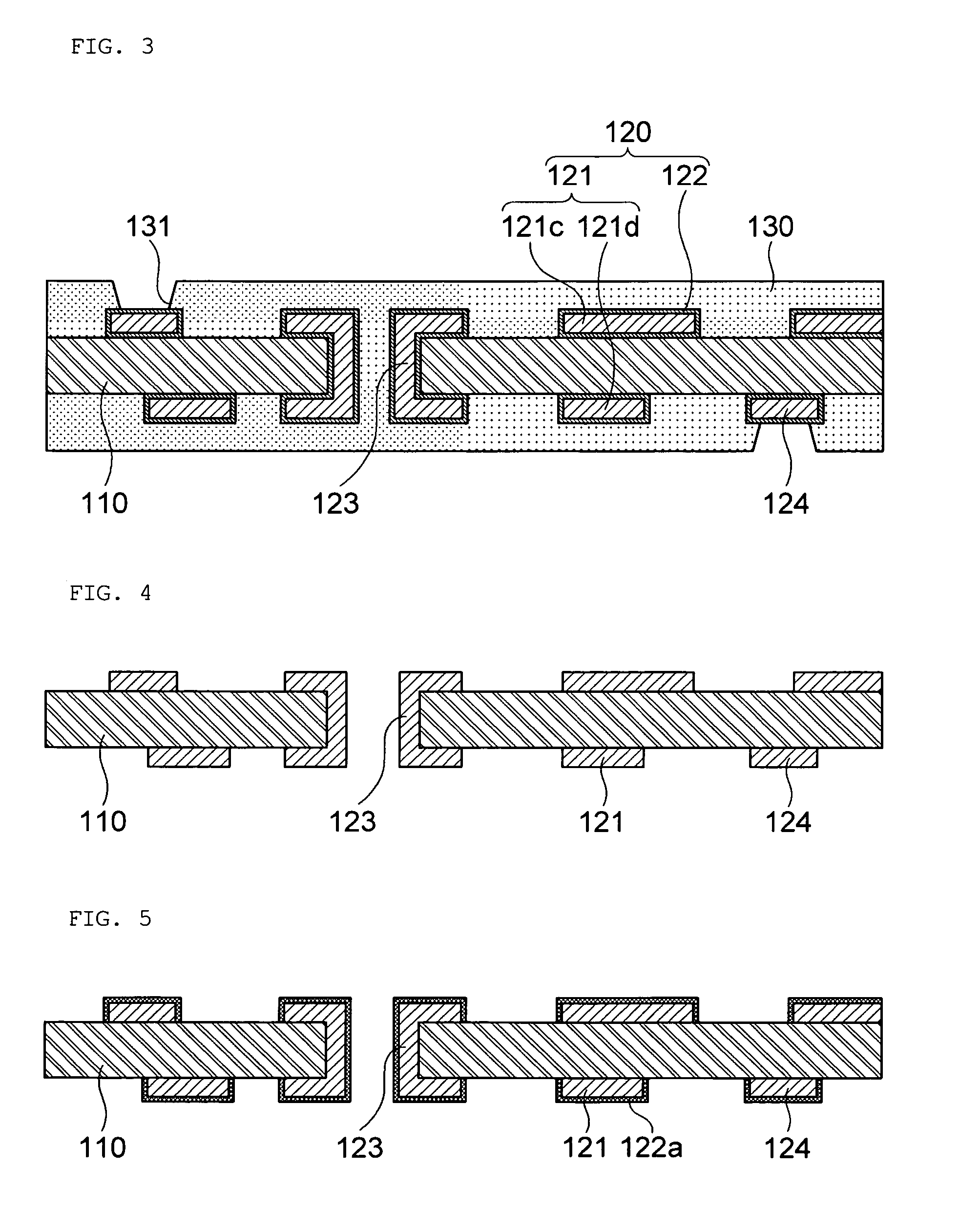
[0049]FIG. 3 is a cross-sectional view of a printed circuit substrate according to the present invention.

[0050]Referring to FIG. 3, the printed circuit substrate according to the third embodiment of the present invention may include a circuit layer 120 that is disposed on a first insulating layer 110. Herein, the circuit layer 120 may include a circuit pattern 121 and a barrier layer 122 that is disposed on one surface of the circuit pattern 121.

[0051]The barrier layer 122 may further be interposed between the first insulating layer 110 and the circuit pattern 121. That is, the barrier layer 122 may be formed to cover all surfaces of the circuit pattern 121. Herein, the barrier layer 122 can prevent conductive filaments from growing downward the circuit pattern 121, thereby making it possible to prevent a short circuit defect between third and fourth circuit patterns 121c and 121d that are disposed on the upper and lower portions, respectively. Therefore, although the thickness of t...


PUM

PropertyMeasurementUnit
thicknessaaaaaaaaaa
thicknessaaaaaaaaaa
thicknessaaaaaaaaaa

Abstract

Disclosed herein are a printed circuit substrate and a method of manufacturing the same. The printed circuit substrate includes an insulating layer, and a circuit layer that includes a circuit pattern disposed on the insulating layer and a barrier layer that is disposed to cover at least one surface of the circuit pattern and suppresses electrochemical migration from the circuit pattern, thereby making it possible to achieve high-density and secure reliability, and the method of manufacturing the same.

Description

CROSS REFERENCE TO RELATED APPLICATION[0001]This application claims the benefit of Korean Patent Application No. 10-2010-0036452, filed on Apr. 20, 2010, entitled “Printed circuit substrate and method of manufacturing the same”, which is hereby incorporated by reference in its entirety into this application.BACKGROUND OF THE INVENTION[0002]1. Technical Field[0003]The present invention relates to a printed circuit substrate and a method of manufacturing the same, and more particularly, to a printed circuit substrate having a barrier layer that suppresses electrochemical migration from a circuit pattern and a method of manufacturing the same.[0004]2. Description of the Related Art[0005]A printed circuit substrate, which serves to electrically connect electronic components to each other, is a core component of electronic equipment. The printed circuit substrate can be applied to electronic equipment used in the external environment, for example, a portable terminal, electronic componen...

Claims


Application Information

Patent Timeline
Patent Type & Authority Patents(United States)
IPC IPC(8): H05K1/03H05K3/36
CPCH05K3/244H05K2201/0338Y10T29/49126Y10T29/49155H05K2201/0769
Inventor PARK, HYUNG WOOKJOO, YOUNG CHANGMIN, HONG SEOKKO, YOUNG GWANRYU, CHANG SUPLEE, HO YOUNGLEE, SHIN BOKJUNG, MIN SUK
Owner SAMSUNG ELECTRO MECHANICS CO LTD
Learn More