Compensation orthodontic archwire design

Inactive Publication Date: 2013-04-09
ORAMETRIX
View PDF1 Cites 34 Cited by
  • Summary
  • Abstract
  • Description
  • Claims
  • Application Information

AI Technical Summary

Problems solved by technology

Often, the initially designed customized archwire for moving a patient's teeth from malocclusion to the desired target set-up reaches an equilibrium without achieving the planned treatment goal.

Method used


Image

  • Compensation orthodontic archwire design
  • Compensation orthodontic archwire design
  • Compensation orthodontic archwire design

Examples


Embodiment Construction

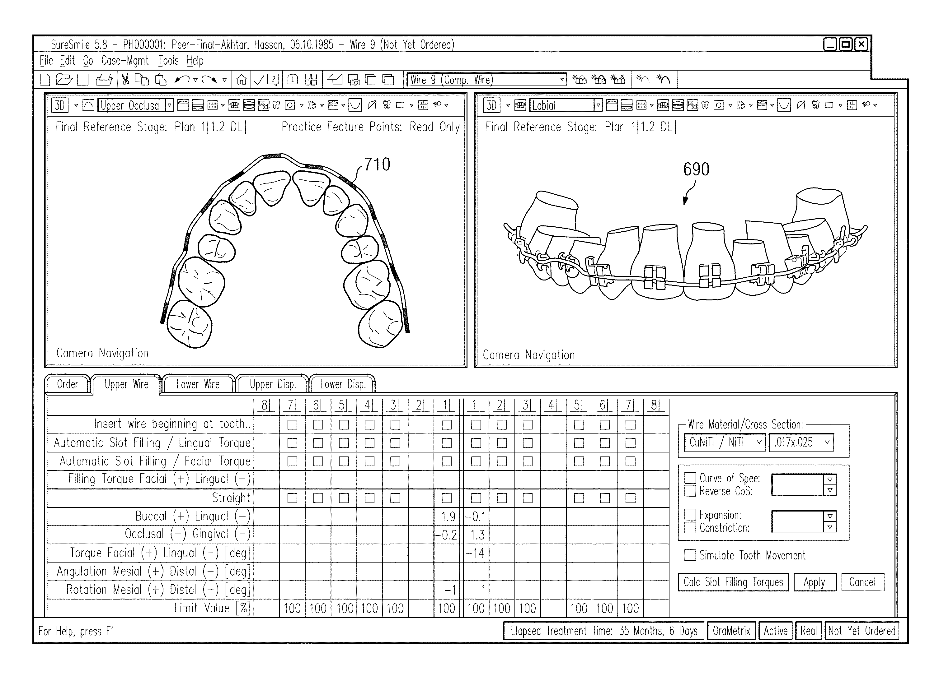
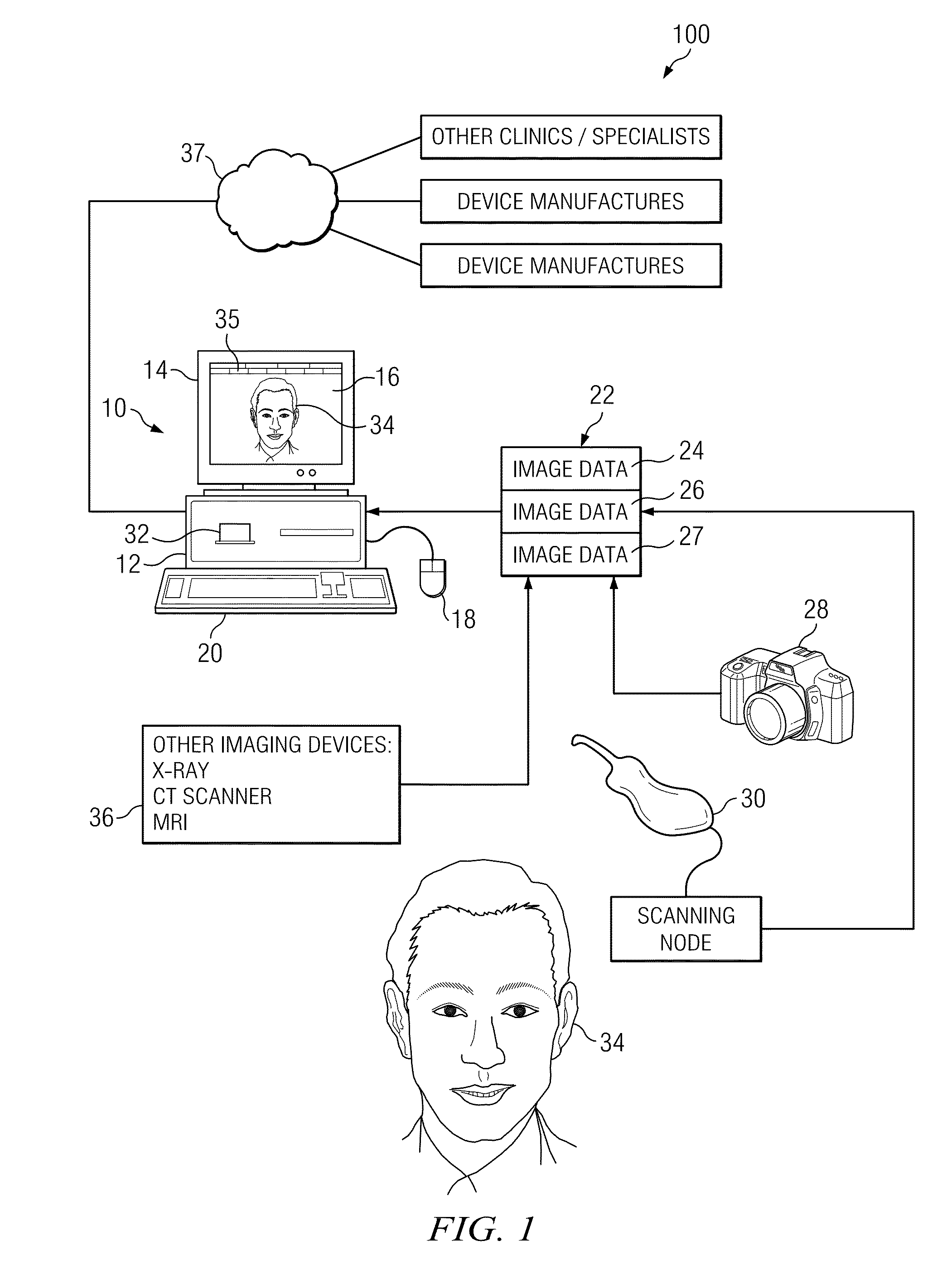
[0034]Before describing the features of this invention in detail, an overview of a unified workstation will be set forth initially. The workstation provides software features that create two dimensional and / or three-dimensional virtual patient model on a computer, which can be used for purposes of treatment planning in accordance with a presently preferred embodiment.

[0035]Many of the details and computer user interface tools which a practitioner may use in adjusting tooth position, designing appliance shape and location, managing space between teeth, and arriving at a finish tooth position using interaction with a computer storing and displaying a virtual model of teeth are set forth in the prior application Ser. No. 09 / 834,412 filed Apr. 13, 2001, and in published OraMetrix patent application WO 01 / 80761, the contents of which are incorporated by reference herein. Other suites of tools and functions are possible and within the scope of the invention. Such details will therefore be...


PUM


Abstract

Method and workstation automatically designing an arch-wire including compensations for auxiliary appliances or biological constraints exerting unknown forces to achieve a pre-planned treatment goal are disclosed. The adjusted customized arch-wire is designed after an initial customized arch-wire has been used to treat a patient and is at or near equilibrium. The initial custom arch-wire is first designed by producing a 3D computer-based, geometrical model of a patient's dentition, locating brackets on the digital tooth model, moving the digital tooth models to planned final positions and orientations, and then calculating a wire which fits in the slots of the brackets while the teeth are in their planned final positions and exerts no forces on the brackets. After a period of time the teeth will move under the force of the wire and will eventually move into positions such that the forces from all appliances and biological systems are in equilibrium. If the teeth are not in the final planned positions at that point in time, the adjusted custom arch-wire is designed and applied.

Description

CROSS-REFERENCE TO RELATED APPLICATIONS[0001]This application is related to application Ser. No. 12 / 772,133, filed Apr. 30, 2010, Title: BRACKET-SLOT-TO-WIRE PLAY COMPENSATION ARCHWIRE DESIGN, and application Ser. No. 10 / 428,461, filed May 2, 2003, pending, which is a continuation-in-part of application Ser. No. 09 / 834,412, filed Apr. 13, 2001, now issued as U.S. Pat. No. 6,632,089, the entire contents of which are incorporated by reference herein. This application is also related to patent application Ser. No. 10 / 429,123, filed May 2, 2003, now issued as U.S. Pat. No. 7,234,937, the entire contents of which are incorporated by reference herein. This application is also related to application Ser. No. 09 / 835,039, filed Apr. 13, 2001, now issued as U.S. Pat. No. 6,648,640, the entire contents of which are incorporated by reference herein.BACKGROUND OF THE INVENTION[0002]A. Field of the Invention[0003]This invention relates generally to the field of orthodontics. More particularly, th...

Claims


Application Information

Patent Timeline
Patent Type & Authority Patents(United States)
IPC IPC(8): G06F19/00
CPCA61C7/002A61C7/20
Inventor GETTO, PHILLIPSACHDEVA, ROHITSPORBERT, PEER
Owner ORAMETRIX
Why Eureka
Try Eureka