
Deployment pattern realization with models of computing environments

a computing environment and deployment pattern technology, applied in knowledge representation, instruments, analogue processes of specific applications, etc., can solve the problems of not having first-hand knowledge of the developed artifacts of the development environment from which a new application is developed is often different from the operation environment, and the architects within the operations environment are typically burdened with the responsibility of carrying the developed application

Inactive Publication Date: 2013-04-09
GLOBALFOUNDRIES INC
View PDF68 Cites 18 Cited by
  • Summary
  • Abstract
  • Description
  • Claims
  • Application Information

AI Technical Summary

Benefits of technology

The present invention provides a way to match deployment patterns in a computing environment model. This is done by creating a model of the environment and then comparing it to a realization pattern that captures the deployment parameters. The result is a match or mismatch, which can be used to make informed decisions. This technology helps to optimize resource allocation and improve the overall efficiency of computing environments.

Problems solved by technology

However, the development environment from which a new application is developed is often different from an operations environment, e.g., a data center, which deploys the developed applications.
In this regard, architects within the operations environment are typically burdened with the responsibility of carrying the developed application into operations.
However, the architects within the operations environment often do not have first-hand knowledge of the developed artifacts, e.g., the details, requirements specifications, configuration, etc., associated with the application to be deployed.

Method used


Image

  • Deployment pattern realization with models of computing environments
  • Deployment pattern realization with models of computing environments
  • Deployment pattern realization with models of computing environments

Examples


Embodiment Construction

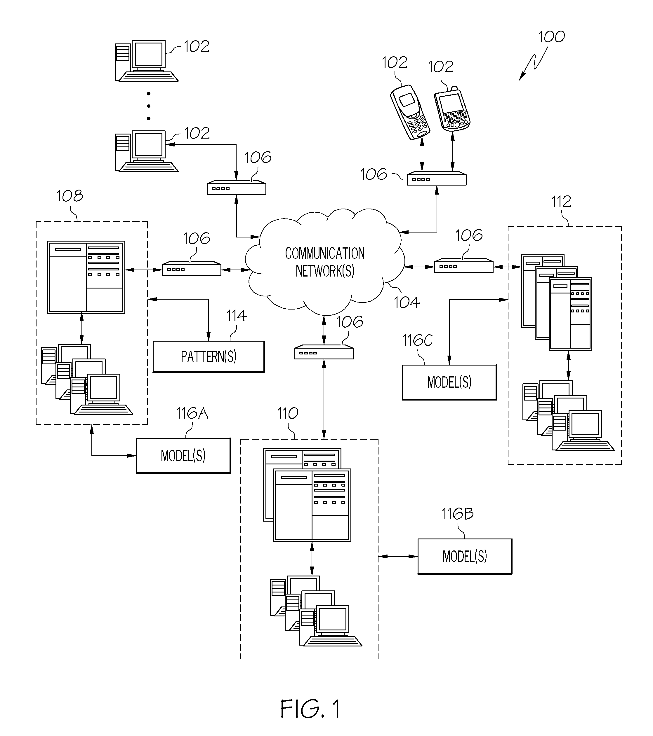
[0013]According to aspects of the present invention, pattern matching capabilities are provided to determine whether a model of a computing environment contains a sub-model that realizes, i.e., matches, a pattern of interest. In general, such problems will be referred to herein as Deployment Pattern Matching problems. For example, a pattern of interest may comprise a given information technology (IT) solution template, e.g., a template that defines the hardware, software and relationships necessary to deploy a given solution. A pattern of interest may also be utilized to specify a deployment compliance pattern, such as a pattern that defines hardware and software necessary for some specified compliance criteria. In this regard, more complex compliance requirements may be specified by a composition of two or more compliance patterns. Accordingly, such pattern matching capabilities may be utilized, for example, in the context of deployment planning as will be described in greater deta...


PUM


Abstract

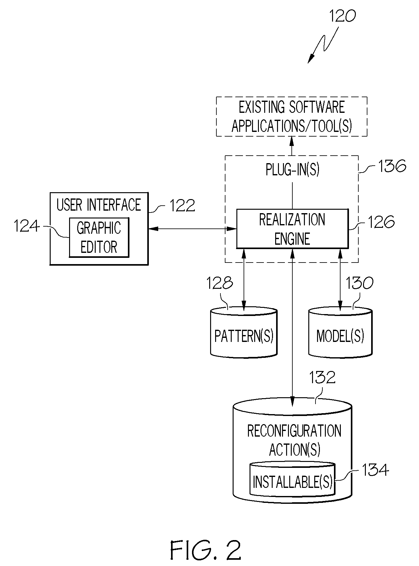
Deployment pattern matching is implemented by accessing a target computing environment model that captures environment modeling parameters relating to resources and resource-resource relationships of a corresponding computing environment and expressing the target computing environment model as a model graph defined by target resource elements and resource-to-resource relationship links. Deployment pattern matching is further implemented by accessing a realization pattern that captures deployment parameters relating to resources and resource-resource relationships of a deployment of interest and expressing the realization pattern as a pattern graph defined by conceptual resource elements and constraints arranged by resource-to-resource relationship links and constraint links. The realization pattern is then evaluated against the target computing environment model by executing at least one pattern matching algorithm that attempts to match the pattern graph to the model graph and information corresponding to results of the evaluation are conveyed.

Description

BACKGROUND OF THE INVENTION[0001]The present invention relates to systems, methods and computer program products for implementing pattern matching capabilities within models of computing environments.[0002]In a typical application development environment, software architects create software applications using conventional development tools. However, the development environment from which a new application is developed is often different from an operations environment, e.g., a data center, which deploys the developed applications. In this regard, architects within the operations environment are typically burdened with the responsibility of carrying the developed application into operations. However, the architects within the operations environment often do not have first-hand knowledge of the developed artifacts, e.g., the details, requirements specifications, configuration, etc., associated with the application to be deployed.[0003]Accordingly, in a deployment planning process, comp...

Claims


Application Information

Patent Timeline
Patent Type & Authority Patents(United States)
IPC IPC(8): G06F17/00G06N5/02
CPCG06N5/02
Inventor ARNOLD, WILLIAM C.EILAM, TAMARKALANTAR, MICHAEL H.KONSTANTINOU, ALEXANDER V.TOTOK, ALEXANDER A.
Owner GLOBALFOUNDRIES INC
Learn More