
Apparatus and method for transmitting/receiving downlink data channel signal transmission information in cellular radio communication system using cooperative multi-point scheme

Active Publication Date: 2013-07-11
SAMSUNG ELECTRONICS CO LTD
View PDF20 Cites 64 Cited by
  • Summary
  • Abstract
  • Description
  • Claims
  • Application Information

AI Technical Summary

Benefits of technology

The present invention aims to solve problems and disadvantages in cellular radio communication systems by providing an apparatus and method for transmitting / receiving downlink data channel signal transmission information in a cellular radio communication system using a Cooperative Multi-Point (CoMP) scheme. The technical effects of this invention include improving data transmission efficiency and reliability in cellular networks, reducing interference between different transmission points, and improving overall network performance.

Problems solved by technology

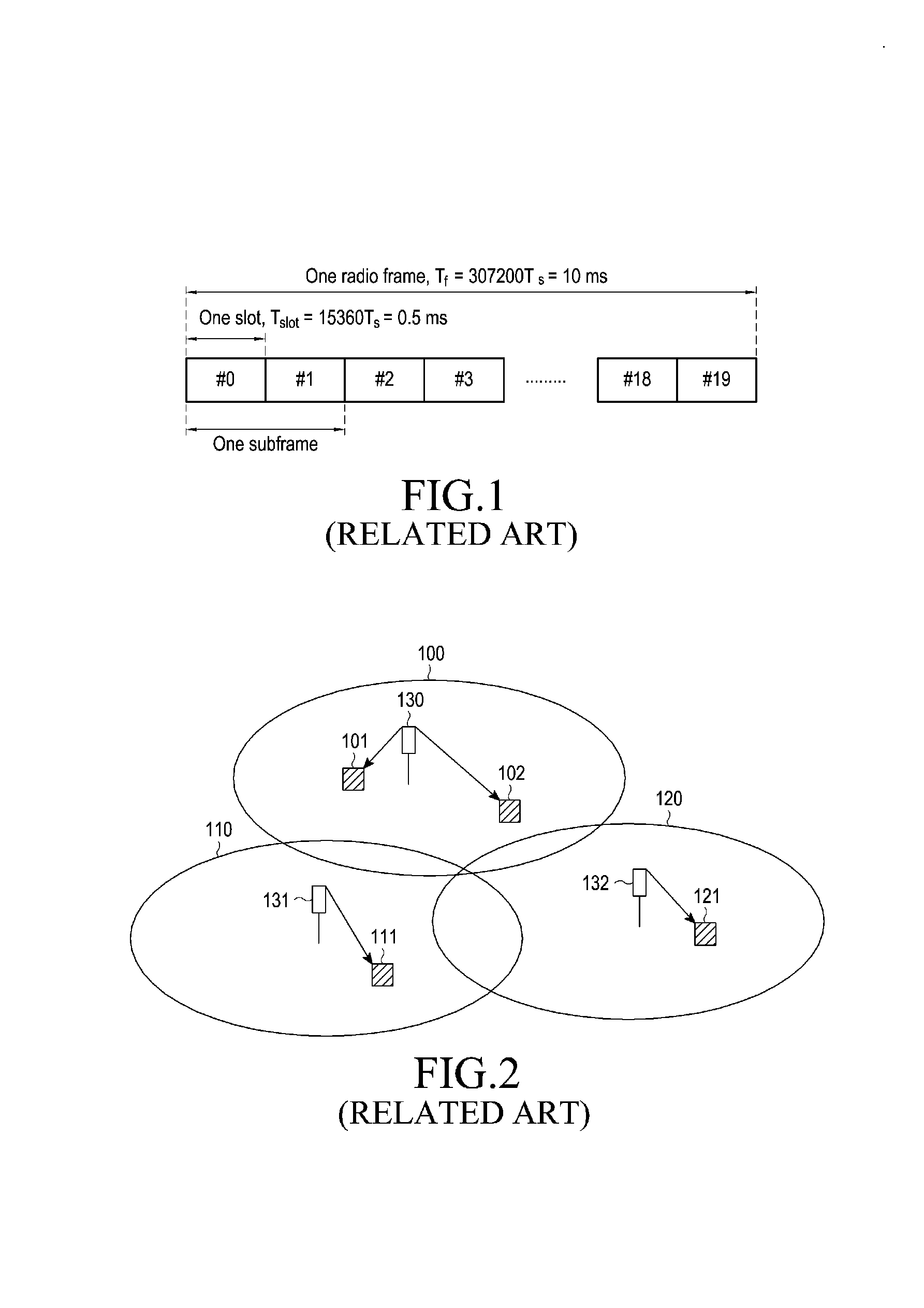
That is, if the channel status is bad, the signal transmission apparatus may keep a reception error probability in a target reception error probability which the signal transmission apparatus targets by decreasing the amount of data packets to be transmitted.
On the other hand, if the channel status is good, the signal transmission apparatus may keep the reception error probability in the target reception error probability and effectively transmit many data packets by increasing the amount of data packets to be transmitted.
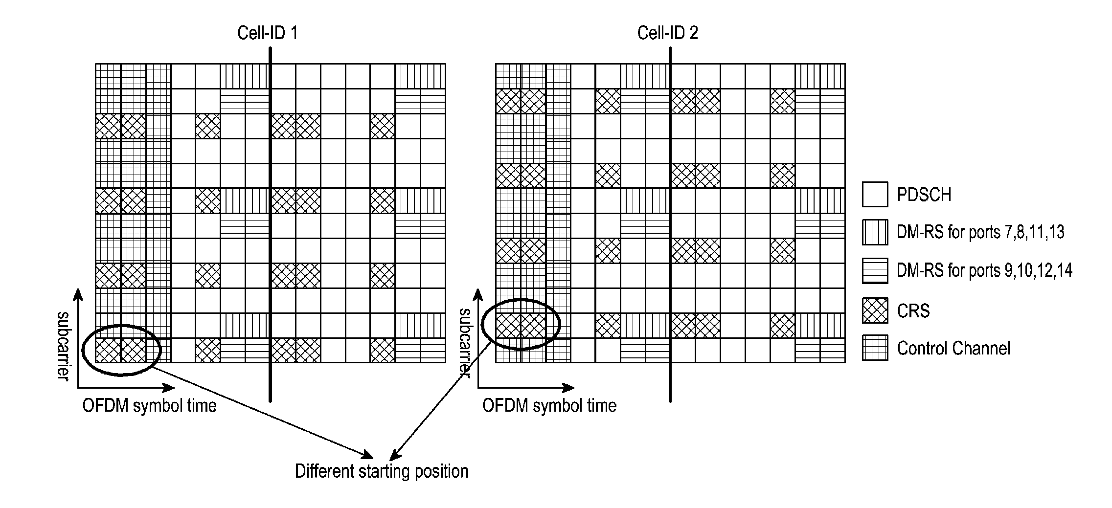
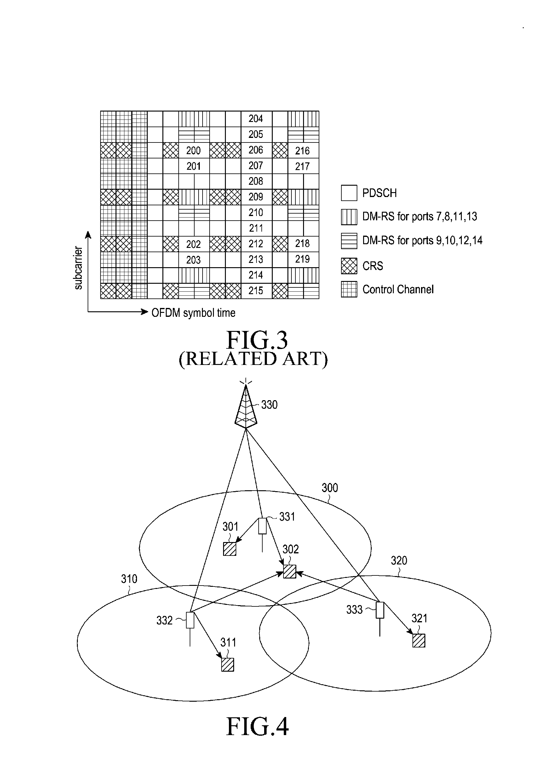
In a cellular radio communication system in FIG. 2, there is a limitation for providing a high data rate to a UE located at a cell boundary due to interference from another cell.
So, in a cellular radio communication system of the related art, it is possible that a relatively high data rate is provided to a UE located relatively close to a cell center, however, it is difficult for a high data rate to be provided to a UE located at a relatively far distance from a cell center.

Method used


Image

  • Apparatus and method for transmitting/receiving downlink data channel signal transmission information in cellular radio communication system using cooperative multi-point scheme
  • Apparatus and method for transmitting/receiving downlink data channel signal transmission information in cellular radio communication system using cooperative multi-point scheme
  • Apparatus and method for transmitting/receiving downlink data channel signal transmission information in cellular radio communication system using cooperative multi-point scheme

Examples


exemplary embodiment # 1

Exemplary Embodiment #1

[0145]FIG. 9 is a flowchart illustrating a method for receiving a PDSCH signal in a UE in a cellular radio communication system using a CoMP scheme according to an exemplary embodiment #1 of the present invention.

[0146]Prior to a description for FIG. 9, in the exemplary embodiment #1 of the present invention, a BS transmits a downlink scheduling information through a Physical Downlink Control Channel (PDCCH), and the downlink scheduling information includes cell information used for a PDSCH signal transmission. A UE receives a PDSCH signal based on a PDSCH resource mapping scheme of a related cell after detecting that the PDSCH signal transmission occurs in which cell using the cell information.

[0147]Referring to FIG. 9, a UE receives Measurement Set Information (MSI) and MBSFN Sub-frame Configuration Information (SCI) from a BS in step 911. The BS transmits the MBSFN SCI to the UE using various schemes, and a description for the various schemes is provided be...

exemplary embodiment # 2

Exemplary Embodiment #2

[0167]FIG. 10 is a flowchart illustrating a method for receiving a PDSCH signal in a UE in a cellular radio communication system using a CoMP scheme according to an exemplary embodiment #2 of the present invention.

[0168]Prior to a description for FIG. 10, in the exemplary embodiment #2 of the present invention, a BS transmits a downlink scheduling information through a PDCCH, and the downlink scheduling information includes cell information used for a PDSCH signal transmission. A UE receives a PDSCH signal based on a PDSCH resource mapping scheme of a related cell after detecting that the PDSCH signal transmission occurs in which cell using the cell information.

[0169]Referring to FIG. 10, a UE receives MSI and MBSFN SCI of cells which allocate CSI-RS resources included in a measurement set from a BS in step 1011. The UE receives PDSCH scheduling information through a PDCCH from the BS, and detects information on a cell which transmits a PDSCH signal using the ...

exemplary embodiment # 3

Exemplary Embodiment #3

[0182]FIG. 11 is a flowchart illustrating a method for receiving a PDSCH signal in a UE in a cellular radio communication system using a CoMP scheme according to an exemplary embodiment #3 of the present invention.

[0183]Prior to a description for FIG. 11, in the exemplary embodiment #3 of the present invention, a UE receives a PDSCH signal through remaining resources except for all CRS resources, a SYNC signal resource and a PBCH resource after detecting MBSFN SCI for cells which allocate CSI-RS resources included in a measurement set.

[0184]Referring to FIG. 11, a UE receives MSI and MBSFN SCI of cells which allocate CSI-RS resources included in a measurement set from a BS in step 1111. The BS transmits MBSFN SCI for each cell as described before with reference to the exemplary embodiment #1 of the present invention, so a detailed description thereof will be omitted herein. The UE receives PDSCH scheduling information through a PDCCH from the BS in step 1113. ...


PUM


Abstract

An apparatus and a method for transmitting / receiving downlink data channel signal transmission information in a cellular radio communication system using a Cooperative Multi-Point (COMP) scheme are provided. In the downlink data channel signal transmission information transmission method, a Base Station (BS) transmits downlink data channel signal transmission information including information related to Resource Elements (REs) scheduled for a downlink data channel signal transmission to a User Equipment (UE), and transmits downlink data channel signal non-transmission information including information related to REs through which a downlink data channel signal is not transmitted among the REs scheduled for the downlink data channel signal transmission to the UE.

Description

CROSS-REFERENCE TO RELATED APPLICATIONS[0001]This application claims the benefit under 35 U.S.C. §119(e) of a United States Provisional Application filed in the United States Patent and Trademark Office on Feb. 17, 2012 and assigned Ser. No. 61 / 600,192, a United States Provisional Application filed in the United States Patent and Trademark Office on Feb. 24, 2012 and assigned Ser. No. 61 / 602,741, a United States Provisional Application filed in the United States Patent and Trademark Office on Apr. 13, 2012 and assigned Ser. No. 61 / 623,768, a United States Provisional Application filed in the United States Patent and Trademark Office on Apr. 17, 2012 and assigned Ser. No. 61 / 625,252, and a United States Provisional Application filed in the United States Patent and Trademark Office on Jun. 21, 2012 and assigned Ser. No. 61 / 662,534, and the benefit under 35 U.S.C. §119(a) of a Korean patent application filed on Jan. 11, 2012 in the Korean Intellectual Property Office and assigned Seria...

Claims


Application Information

Patent Timeline
IPC IPC(8): H04W72/04
CPCH04L5/0007H04L5/003H04W72/04H04L5/0073H04L5/0048H04B7/024H04L5/0035H04W72/23
Inventor LEE, HYO-JINKIM, YOUN-SUNKIM, KI-ILJI, HYOUNG-JUCHO, JOON-YOUNGLEE, JU-HO
Owner SAMSUNG ELECTRONICS CO LTD
Learn More