Method for determining the position of a mobile station

a mobile station and position technology, applied in direction finders using radio waves, instruments, wireless communication, etc., can solve the problems of inability to determine the position of a mobile station stolen, inaccuracy, and unnecessary handover operations, so as to achieve greater accuracy, avoid unnecessary handover operations, and improve accuracy

Inactive Publication Date: 2005-02-01
NOKIA NETWORKS OY
View PDF28 Cites 86 Cited by
  • Summary
  • Abstract
  • Description
  • Claims
  • Application Information

AI Technical Summary

Benefits of technology

The most significant advantage with the solution of the invention is thus that the position of the mobile station, that is both its direction and distance from the base station, can be determined with significantly greater accuracy than previously, which

Problems solved by technology

The most significant problem with this known solution is its inaccuracy.
Thus temporary radio disturbances can lead to an unnecessary handover operation, i.e. the mobile station is transferred from one cell to another when the signal level or quality falls below a predetermined level, after which the handover op

Method used


Image

  • Method for determining the position of a mobile station
  • Method for determining the position of a mobile station
  • Method for determining the position of a mobile station

Examples


Embodiment Construction

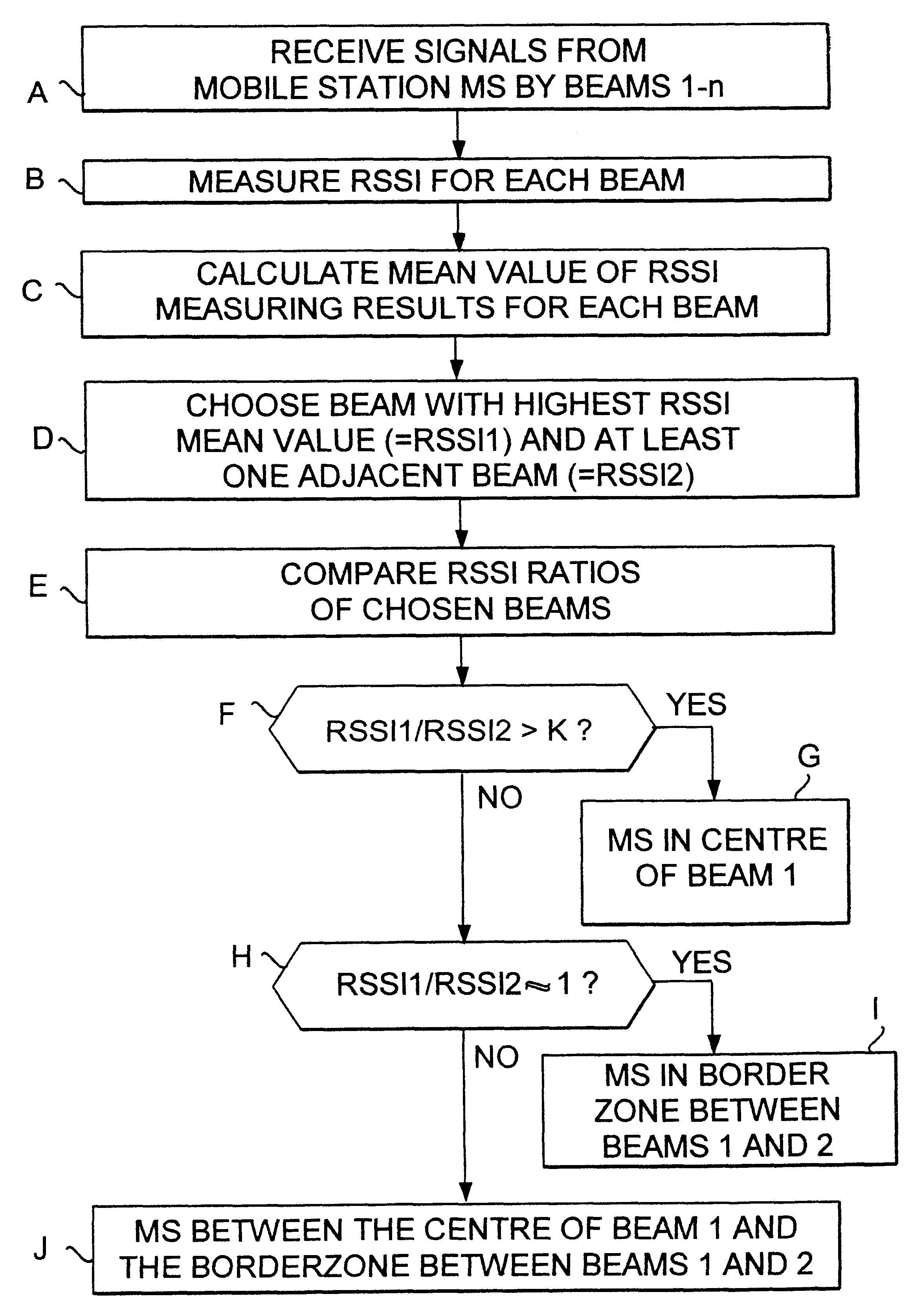
FIG. 1 shows a block diagram of a first preferred embodiment of the method of the invention. The block diagram in FIG. 1 can, for example, be applied in a base station of the GSM system to determine the position of a mobile station.

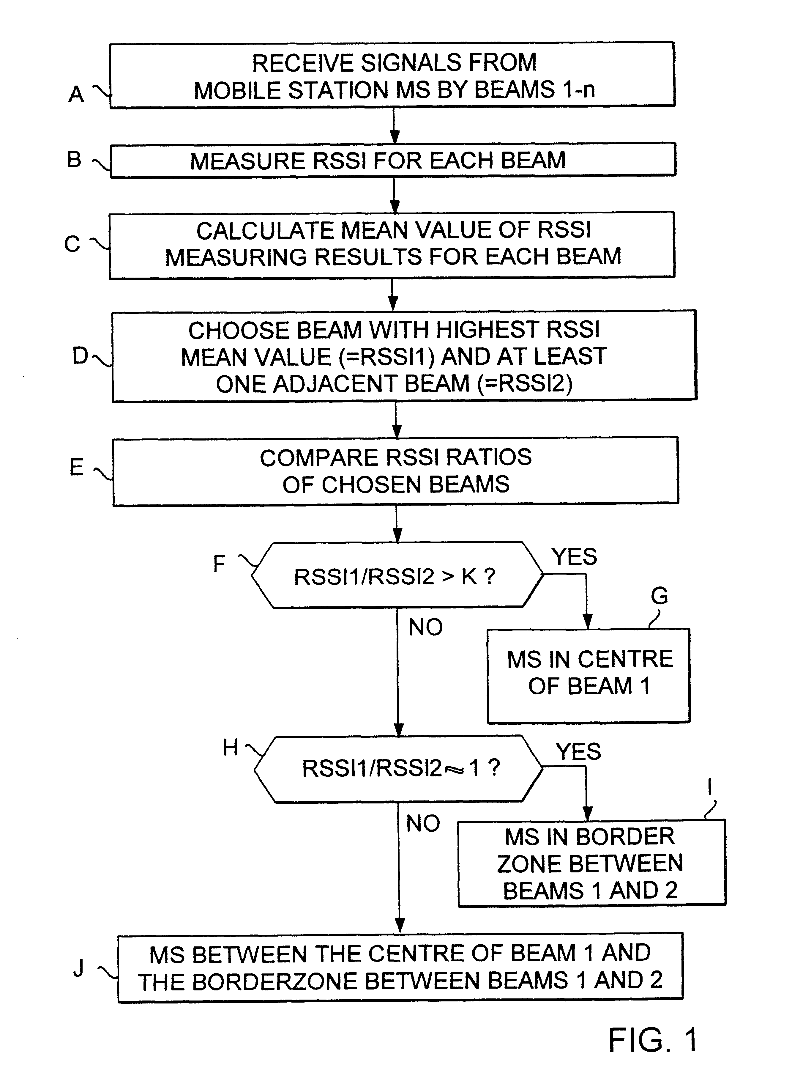
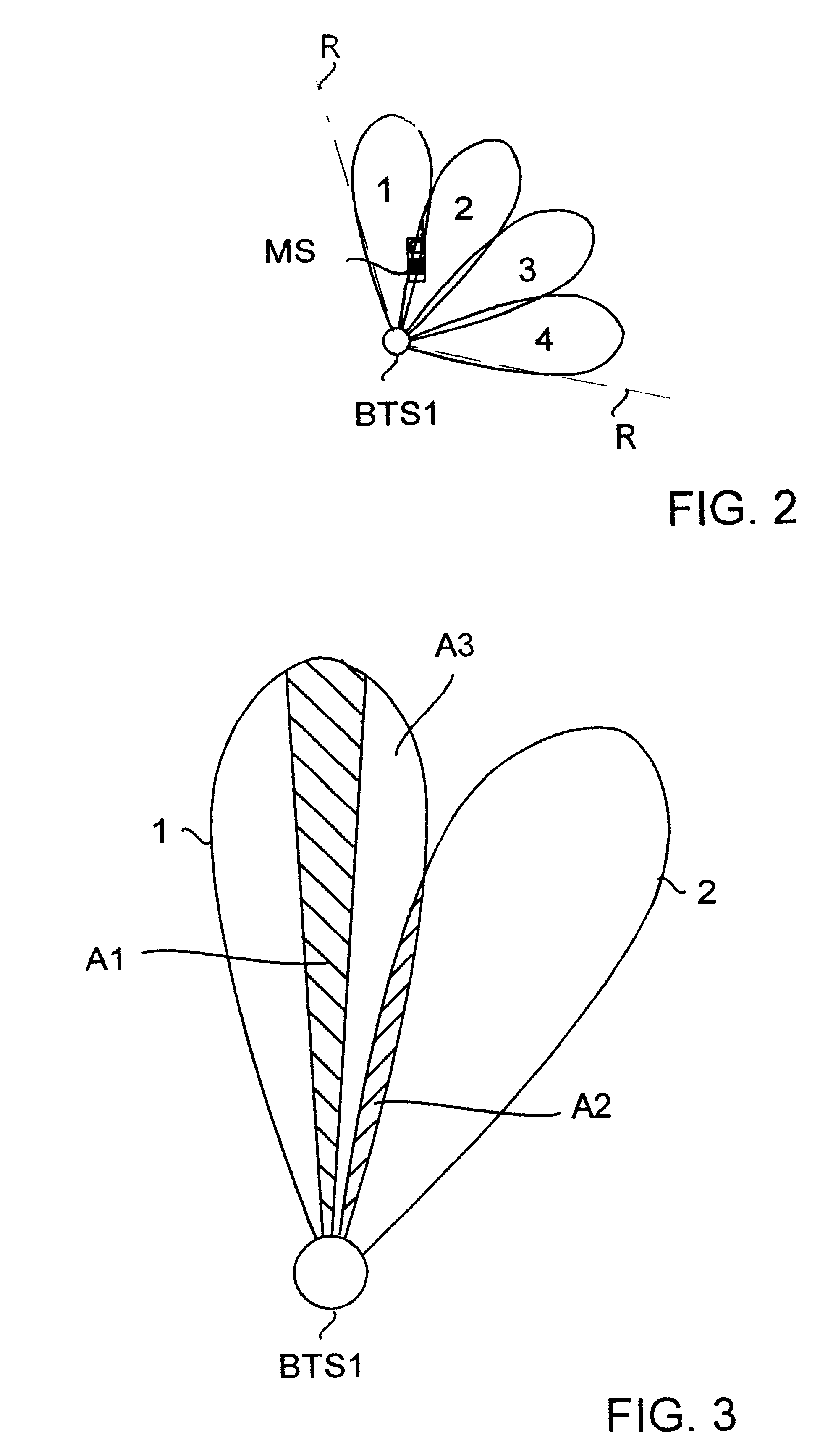
In block A signals are received from a mobile station MS by several antenna beams directed in different directions. The antenna beams used are preferably relatively narrow beams that are directed so that they at least partly overlap (compare with FIG. 2).

In block B the received signal strength indication RSSI of the received signal is measured for the signals received by the respective beams.

In block C a mean value is calculated for the RSSI values measured within a certain time span for each beam. By calculating the mean value for the RSSI values it can be avoided that temporary disturbances influence the locating of the mobile station. For example in the GSM system the time span in question can be chosen so that the mean value is calculated for a few bu...


PUM


Abstract

The present invention relates to a base station of a cellular radio system, which base station comprises antenna equipment for receiving signals from a certain mobile station simultaneously by at least two antenna beams directed in different directions, and measuring equipment for measuring the signal levels of the signals received by the respective antenna beans. For determining the position of the mobile station with greater accuracy the base station is provided with calculating means which are responsive to the measuring equipment to determine the direction from the base station to the mobile station by calculating the relations between the signal levels of the signals for the respective beams.

Description

FIELD OF THE INVENTIONThe invention relates to a method for determining the position of a mobile station located in the coverage area of a base station in a radio system, in which method the base station comprises equipment for receiving signals from the same mobile station simultaneously by at least two antenna beams directed in different directions, and in which method: the signal levels of the signals received by the different antenna beams are measured, the signal levels of the signals received from the same mobile station by the different antenna beams are compared, and the direction to the mobile station in relation to the base station is determined on the basis of the relations between the signal levels measured for the different antenna beams. The invention further relates to a base station of a radio system, which base station comprises antenna equipment for receiving signals from a certain mobile station simultaneously by at least two antenna beams directed in different di...

Claims


Application Information

Patent Timeline
IPC IPC(8): G01S3/28G01S3/14H04Q7/38H04Q7/36G01S5/02H04W64/00
CPCH04W64/00G01S3/28
Inventor PALLONEN, JORMA
Owner NOKIA NETWORKS OY
Why Eureka
Try Eureka