
Information on Reference Signal Structure for Neighboring Cell Measurements

a neighboring cell and information technology, applied in the field of cellular radio communication, can solve the problems of extremely high values and limited multi-cell broadcast/multicast capacity, and achieve the effect of accurate detection of reference signals

Active Publication Date: 2010-05-13
OPTIS WIRELESS TECH LLC
View PDF30 Cites 84 Cited by
  • Summary
  • Abstract
  • Description
  • Claims
  • Application Information

AI Technical Summary

Benefits of technology

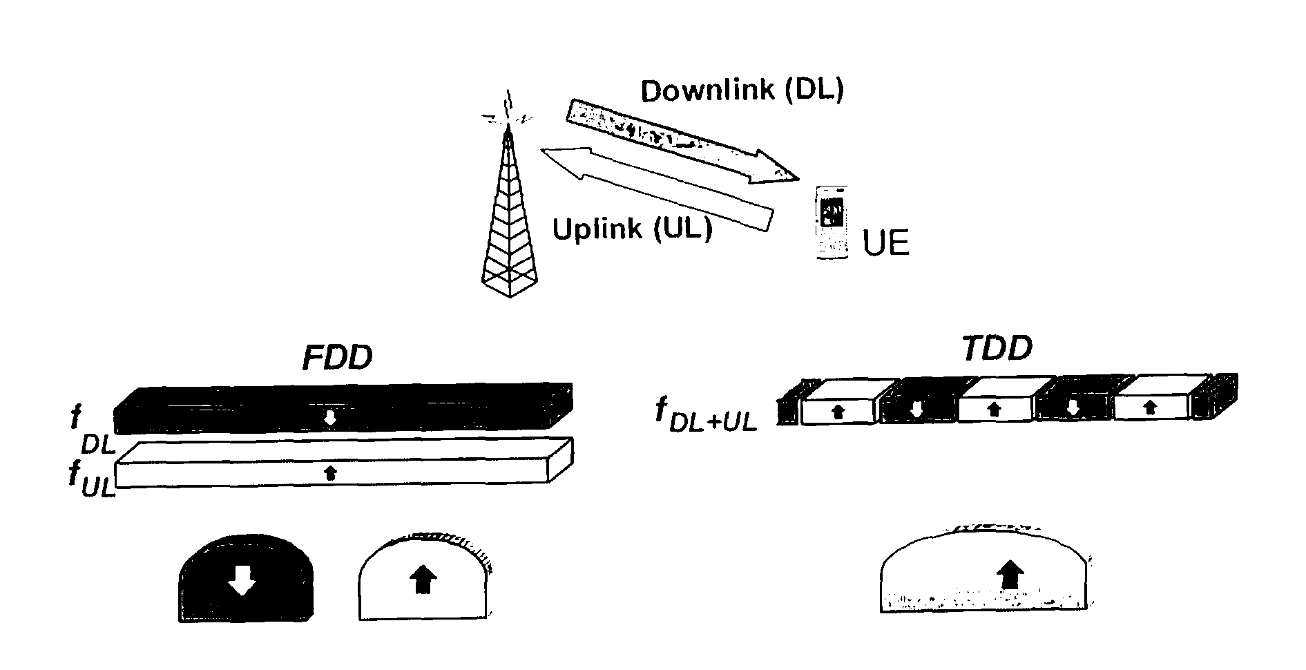
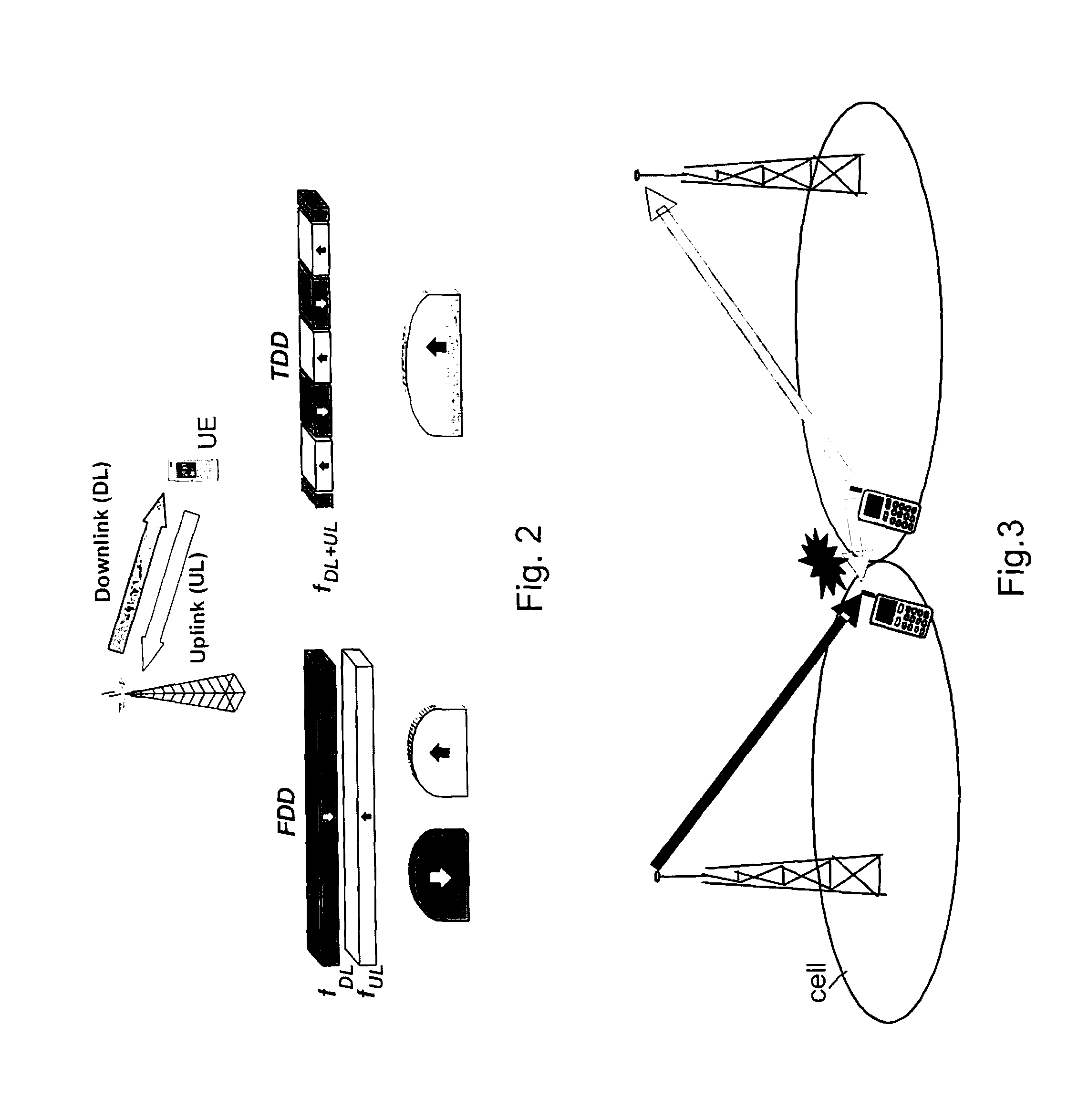
[0020]An advantage of the invention is a terminal will make attempts to detect reference signals only in symbols that are carrying the reference signal. Thereby it is possible to have different regions of cells within which the same multicast information is broadcasted, or within which the same allocation of sub-frames for respectively uplink and downlink transmissions is used. The present invention is particular needed in cells bordering the different regions of cells, to enable the terminals to accurately detect the reference signals of all the neighbour cells.
is a terminal will make attempts to detect reference signals only in symbols that are carrying the reference signal. Thereby it is possible to have different regions of cells within which the same multicast information is broadcasted, or within which the same allocation of sub-frames for respectively uplink and downlink transmissions is used. The present invention is particular needed in cells bordering the different regions of cells, to enable the terminals to accurately detect the reference signals of all the neighbour cells.

Problems solved by technology

Thus, with OFDM, multi-cell broadcast / multicast capacity may eventually only be limited by noise and can then, in case of small cells, reach extremely high values.

Method used


Image

  • Information on Reference Signal Structure for Neighboring Cell Measurements
  • Information on Reference Signal Structure for Neighboring Cell Measurements
  • Information on Reference Signal Structure for Neighboring Cell Measurements

Examples


Embodiment Construction

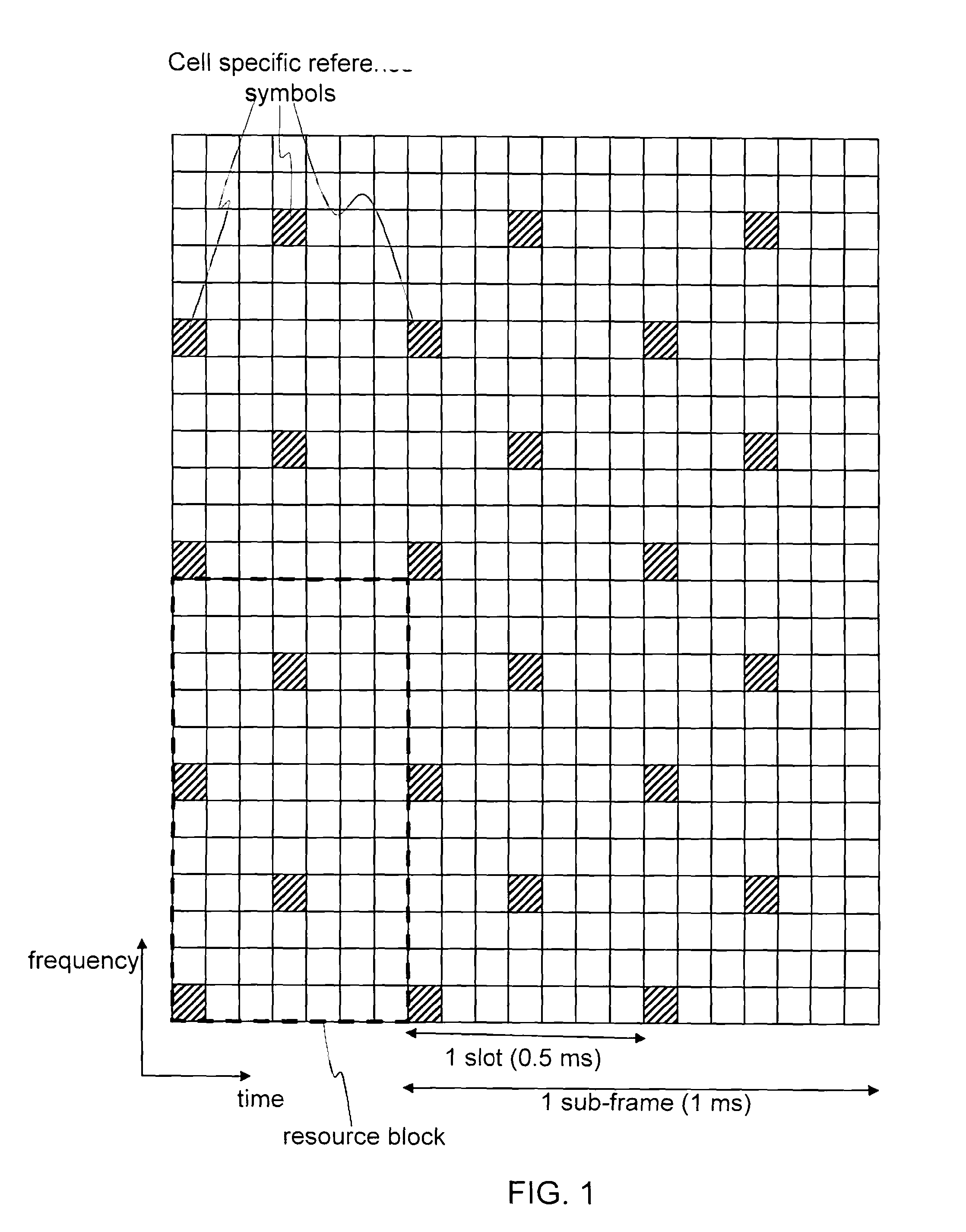
[0031]For neighbour cell measurements the cell specific reference signal shall be used. Informing of the reference signal structure to be used for neighbouring cells measurement separately from the configuration in the serving cell provides several benefits.

[0032]MBSFN transmissions in neighboring cells may use different sub-frames without affecting the possibility to perform accurate neighboring cell measurements. Although using time aligned transmissions for MBSFN is useful in case the full benefits of MBSFN are to be exploited, at the border between different MBSFN regions this is not the case. The invention makes it possible to set up different regions of broadcasting the same MBSFN data. Within a region the same sub-frame allocation is used for broadcasting the MBSFN data. Thereby the broadcasting of information of interest only in a specific geographical area can be restricted to that area. FIG. 5 illustrates a number of cells spread in the geography, some of them included in ...


PUM


Abstract

The present invention relates to cellular radio communication and in particular to providing information on neighbour cells to enable terminals to perform neighbour cell measurements. In the prior art the terminal attempts to make neighbour cell measurements in a reference signal structure that is the same in the neighbour cell as in the cell the terminal camps in. The present invention is based on the insight that the reference signal structure may differ between neighbouring cell for example in the situation of an MBSFN area that is restricted to a region of all cells of a radio network, or in the situation of TDD mode being applied there may be different regions with different allocation of sub-frames for transmission in the uplink and downlink directions. The present invention solves the problem by broadcast information in a cell indicative of the reference signal structure in neighbour cells.

Description

TECHNICAL FIELD OF THE INVENTION[0001]The present invention relates to cellular radio communication and in particular to provide information to mobile terminals that enable the terminals to carry out measurements on cells neighbouring a cell the terminals camp in. The invention also relates to a radio base station adapted for providing the information, a mobile terminal and a method for the mobile terminal.DESCRIPTION OF RELATED ART[0002]In the forthcoming evolution of the mobile cellular standards like GSM and WCDMA, new transmission techniques like OFDM are likely to occur. Furthermore, in order to have a smooth migration from the existing cellular systems to the new high capacity high data rate system in existing radio spectrum, the new system has to be able to operate in a flexible bandwidth. An example of such a new flexible cellular system is 3G Long Term Evolution (3G LTE) that can be seen as an evolution of the 3G WCDMA standard. This system will use OFDM as the downlink tra...

Claims


Application Information

Patent Timeline
Patent Type & Authority Applications(United States)
IPC IPC(8): H04W24/00H04W48/12H04W48/20
CPCH04L5/0023H04L5/005H04L25/0206H04L27/2613H04W48/12H04W88/08H04W24/02H04W72/005H04L5/0094H04W72/042H04W48/20H04L25/0204H04W72/23H04W72/30
Inventor PARKVALL, STEFANASTELY, DAVIDDAHLMAN, ERIK
Owner OPTIS WIRELESS TECH LLC
Learn More