Unmanned aerial vehicle having spherical loading portion and unmanned ground vehicle therefor

a technology of unmanned aerial vehicles and loading portions, which is applied in the directions of anchoring installations, launch/towing gear, transportation and packaging, etc., can solve the problems of limited range of travel, limited duration of flight, and rotating wing type unmanned aerial vehicles, so as to reduce the weight of the unmanned ground vehicle

Inactive Publication Date: 2013-04-16
PUSAN NAT UNIV IND UNIV COOPERATION FOUND
View PDF12 Cites 33 Cited by
  • Summary
  • Abstract
  • Description
  • Claims
  • Application Information

AI Technical Summary

Benefits of technology

[0013]Another object of the present invention is to allow an unmanned aerial vehicle to easily take off and land irrespective of whether an unmanned ground vehicle is horizontal.
[0030]The unmanned aerial vehicle of the present invention is advantageous in that it is capable of independent landing / takeoff as well as of coupling landing / takeoff irrespective of whether an unmanned ground vehicle is horizontal. Further, the landed unmanned aerial vehicle can be fixed stably. The unmanned ground vehicle of the present invention is advantageous in that it is capable of aligning an unmanned aerial vehicle always at the same location, although location errors are generated upon landing, by precisely controlling the location of the landed unmanned aerial vehicle. Further, the weight of the unmanned ground vehicle can be reduced weight since it needs no leveling apparatus.

Problems solved by technology

On the other hand, the rotating wing type unmanned aerial vehicle is disadvantageous in that it has limited duration of flight because of its high power consumption, as compared with the fixed wing type unmanned aerial vehicle having duration of flight which is at least 2 or 3 times or a maximum of 10 times in the same takeoff weight.
Meanwhile, the unmanned ground vehicle is less influenced by the weight on board or time taken in traveling than the unmanned aerial vehicle, but has a limited range of traveling because of geographical features or obstacles and so has limited observation and reconnaissance information.
However, since the unmanned ground vehicle usually runs in hazardous areas, the unmanned aerial vehicle rarely maintains a horizontal state when the unmanned aerial vehicle locked in the unmanned ground vehicle attempts takeoff and landing, which makes a smooth takeoff and landing difficult.
However, the leveling apparatus is an additional apparatus for only takeoff and landing, and it increases the weight and complexity of the system.

Method used


Image

  • Unmanned aerial vehicle having spherical loading portion and unmanned ground vehicle therefor
  • Unmanned aerial vehicle having spherical loading portion and unmanned ground vehicle therefor
  • Unmanned aerial vehicle having spherical loading portion and unmanned ground vehicle therefor

Examples


Embodiment Construction

[0039]The present invention will become more evident through the following embodiments. The following embodiments are only illustrative and are not intended to limit or restrict the scope of the present invention.

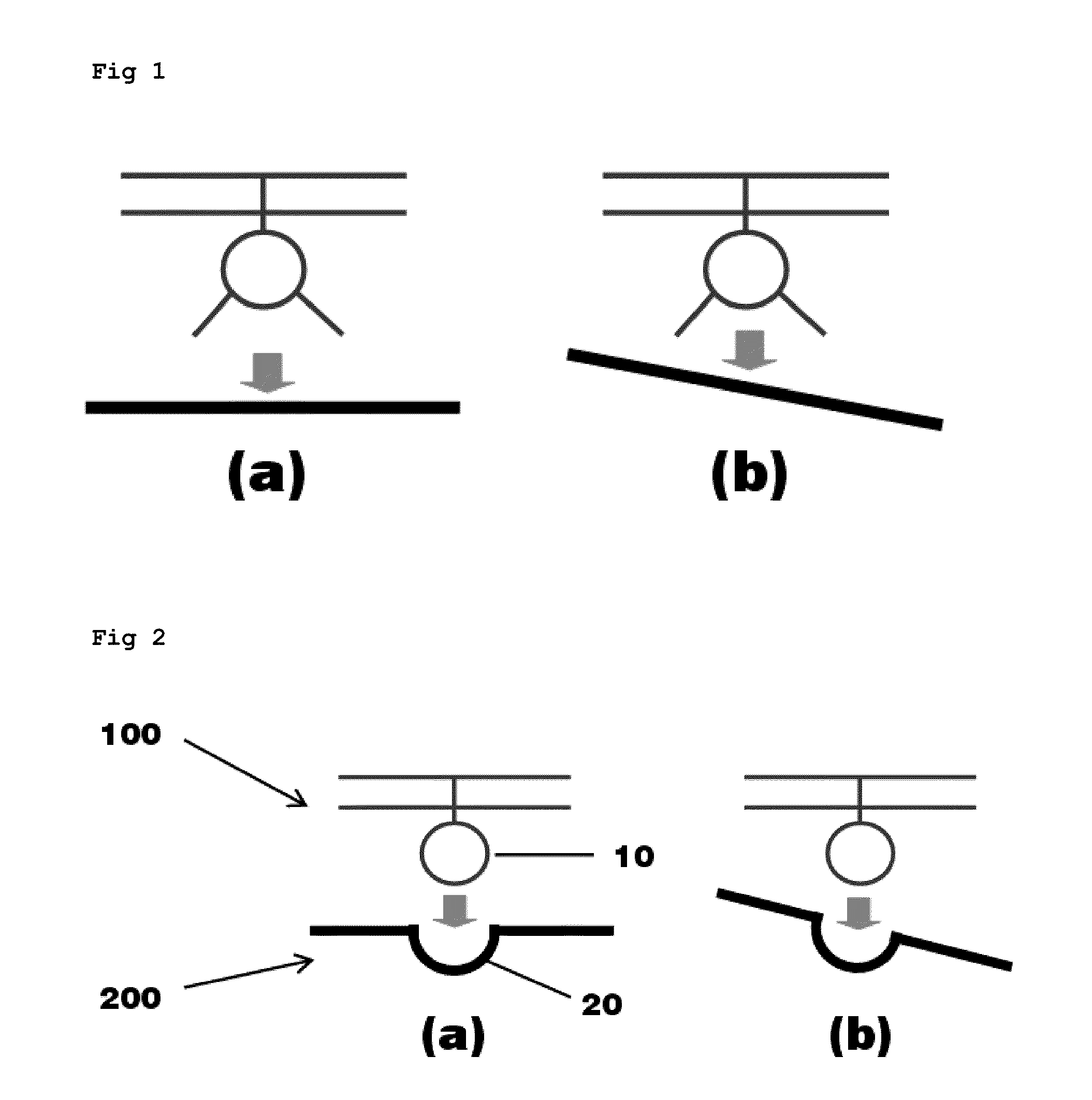
[0040]As shown in FIG. 1a, an unmanned ground vehicle has a flat surface, and an unmanned aerial vehicle lands on and takes off from the flat surface. However, since the unmanned ground vehicle mainly moves on plains or hazardous locations in its practical use, when the unmanned ground vehicle stops in order for the unmanned aerial vehicle to land on or take off therefrom, the surface of the unmanned ground vehicle is inclined as shown in FIG. 1b. It makes it difficult for an unmanned aerial vehicle, having a skid type landing gear (refer to FIG. 1) or a wheel type landing gear, to smoothly land on or take off from the surface of the unmanned ground vehicle.

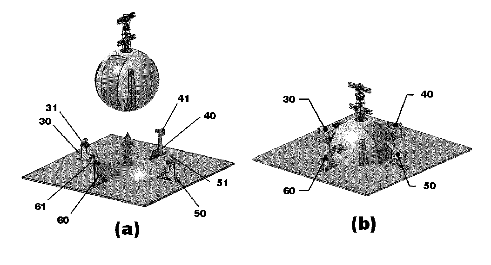
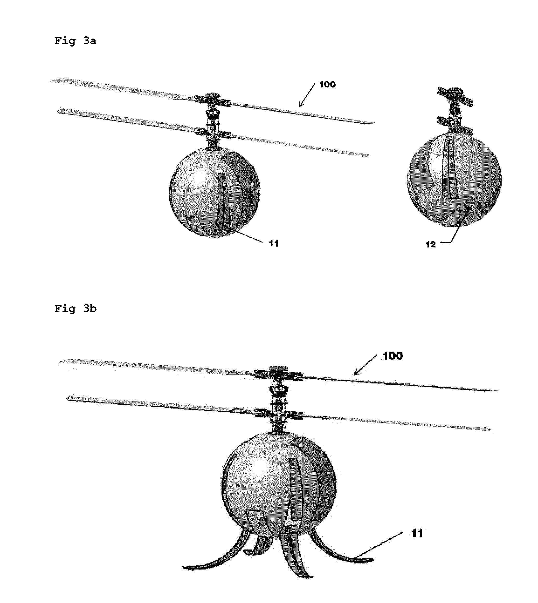
[0041]To solve the above problem, in the present invention, as shown in FIG. 2a, an unmanned aerial vehicle 100 is equ...


PUM


Abstract

An unmanned aerial vehicle equipped with a spherical locking portion for landing on an unmanned ground vehicle is disclosed. The spherical locking portion can be the body of the unmanned aerial vehicle. Further, an unmanned ground vehicle for landing of an unmanned aerial vehicle, comprising a landing portion configured to have some of a spherical locking portion of the unmanned aerial vehicle inserted therein is disclosed.

Description

BACKGROUND OF THE INVENTION[0001]1. Field of the Invention[0002]The present invention relates to an unmanned aerial vehicle and an unmanned ground vehicle having the unmanned aerial vehicle locked therein, and more particularly, to an unmanned aerial vehicle which can easily take off and land irrespective of whether an unmanned ground vehicle is horizontal, and an unmanned ground vehicle having the unmanned aerial vehicle locked therein.[0003]2. Background of the Related Art[0004]An Unmanned Aerial Vehicle (UAV) and an Unmanned Ground Vehicle (UGV) are platforms which can have their postures and locations automatically controlled by on-board computers locked therein and can move to a desired location in response to a command generated by a remote control center. Various forms and sizes of the unmanned aerial vehicles and the unmanned ground vehicles have been developed particularly in the observation and reconnaissance fields.[0005]The unmanned aerial vehicles can be classified into...

Claims


Application Information

Patent Timeline
Patent Type & Authority Patents(United States)
IPC IPC(8): B64F1/12
CPCB64C39/024B64C2201/024B64C2201/042B64C2201/182B64C2201/127B64C2201/208B64C2201/108B64U70/30B64U80/86B64U20/50B64U30/24B64U80/25B64U10/13B64U70/97B64C13/20B64F1/04G05D1/02B64U10/10B64U30/20B64U50/19B64U2101/30
Inventor KANG, BEOM-SOOSONG, WOO-JINKU, TAE-WANBYUN, YOUNG-SEOP
Owner PUSAN NAT UNIV IND UNIV COOPERATION FOUND
Why Eureka
Try Eureka