Closure system

a technology of closure system and knob, which is applied in the direction of snap fasteners, buckles, protective garments, etc., can solve the problems of inability to self-lock, create closure systems that are infinitely adjustable and self-locking, and create closure systems where the torque felt by the knob is constant, etc., to achieve the effect of reducing the number of strap pins

Active Publication Date: 2013-04-23
BOA TECHNOLOGY
View PDF437 Cites 52 Cited by
  • Summary
  • Abstract
  • Description
  • Claims
  • Application Information

AI Technical Summary

Benefits of technology

[0009]Some embodiments of these inventions provide a cam assembly and strap based system for bringing two sides of an article together. The system may also be used to bring multiple sides of an article together, two objects together and / or multiple objects together and / or away from each other. In some embodiments, a cam assembly and strap based closure system may use a logarithmic spiral. When the user inserts the strap into the cam assembly and turns a knob, the strap is driven into the cam assembly. In some embodiments, the pins on the strap engage the cam spirals in the cam assembly. A track insert may pull the strap away from the cam to disengage the strap so that the cam spirals are engaged in reduced number of strap pins compared to the total number of strap pins within the cam assembly.
[0010]In some embodiments, one or more logarithmic spirals cause the strap pins to always be engaged at a constant angle, often self-locking. In addition to being self-locking, the system may be infinitely adjustable and the torque felt by the knob may be constant. The contact angle between the cam and the strap may be varied as desired. In some embodiments, lower contact angles may make the system self-locking. In some embodiments, more than one spiral may be used. Different spirals, such as Archimedean spirals, may be used in some embodiments. In some embodiments, higher contact angles may allow the strap to be driven into the cam assembly more rapidly. In some embodiments, secondary frictional elements, for example detents on the bottom or periphery of the cam or buttons, may be used to make the system self-locking even at higher contact angles. In addition, a detent system may be used to provide an audible click to provide an auditory indication of movement.
[0011]In some embodiments, the system may bring the strap pins into the cam assembly and in parallel to the cam for maximum strength and then use a guide component on a track insert that bends the strap away from the cam in a deliberate and controlled way. The guide component or bend back mechanism may be a tunnel and / or can be an S-shaped bend and / or an arc that pulls the strap away from the cam spirals that drive the strap pins. In some embodiments, the center portion of a spiral may be removed to allow room for this disengagement to occur. This guide component is particularly useful in providing the lowest possible height and / or profile of the housing. The guide component may also allow the strap to be fed into the cam assembly without catching on the cam.

Problems solved by technology

A significant problem with closure systems today is that they lack a self-locking mechanism.
Creating closure systems that are infinitely adjustable and self-locking is especially problematic.
Moreover, creating a closure system where the torque felt by the knob is constant is especially problematic.
Another problem is that closure systems create a force that pries the cam away from the strap, which lowers the strength of the system.
Yet another problem is that closure systems do not prevent the strap from completely falling out of the cam assembly when the strap is loosened.

Method used


Image

  • Closure system
  • Closure system
  • Closure system

Examples


Embodiment Construction

[0049]Numerous technical details are set forth in this description. These details are provided to illustrate some embodiments of the inventions, and are not intended to limit the inventions. Thus, nothing in this detailed description is intended to imply that any particular feature, characteristic, or component of the disclosed system is essential to the inventions.

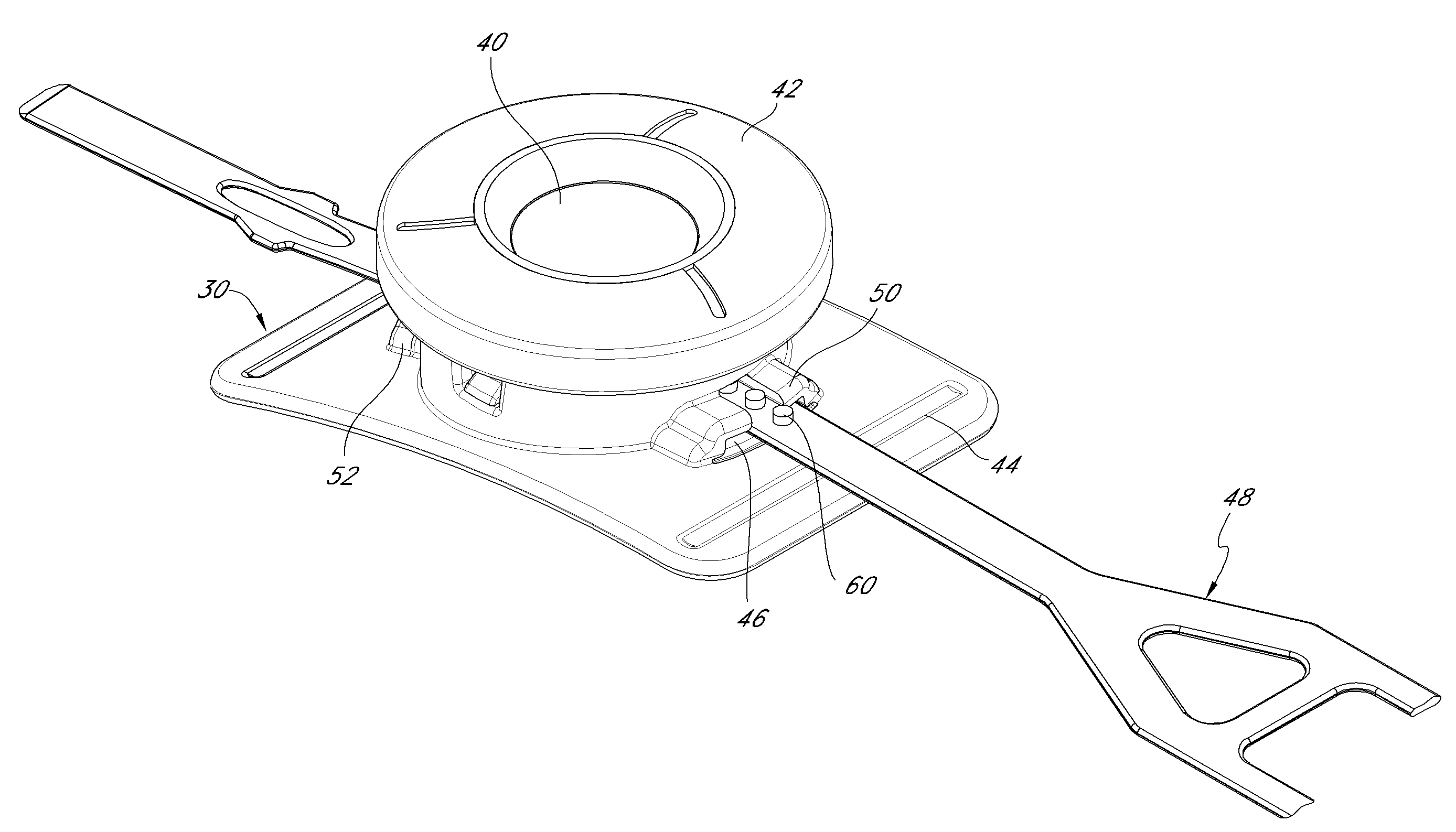
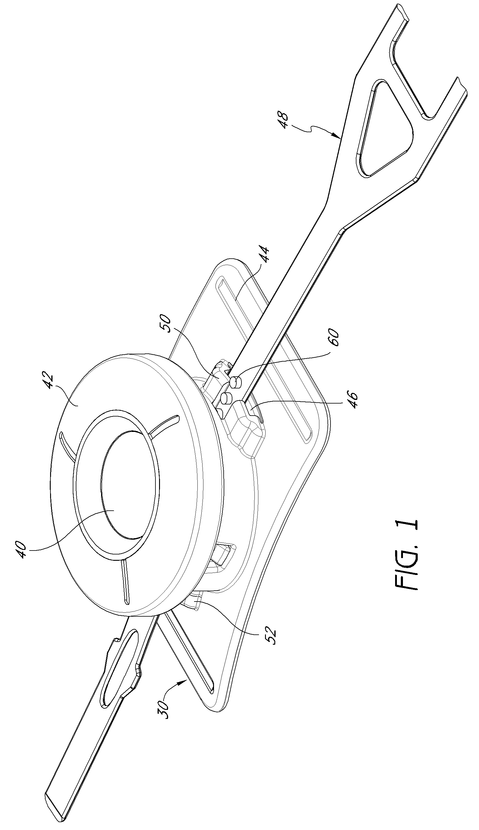
[0050]FIG. 1 illustrates a set of components for implementing a cam assembly and strap based closure system using a spiral from a perspective view, in accordance with some embodiments of the inventions. As depicted in this drawing, a cam assembly 30 may comprise housing 44, a knob 42, a cam 40, and a track insert 46. The cam assembly 30 and housing 44 may be adapted to receive a strap 48. The term “strap” is meant to define a broad term as well as its ordinary meaning. Likewise, the term “cam assembly” is meant to define a broad term as well as its ordinary meaning. The cam assembly 30 and strap 48 may be made from numero...


PUM


Abstract

By way of example, a cam assembly and strap based closure system using a spiral is configured for bringing two sides of an article together. When the user inserts the strap into the cam assembly and turns a knob, the strap is driven into the cam assembly and the strap pins engage one or more cam spirals. The system is configured such that strap pins are engaged at a constant angle which may be self-locking. The system is infinitely adjustable and the torque felt by the knob is constant. The system is configured to be a quick release system and allows rapid insertion of the strap for faster operation.

Description

PRIORITY CLAIM AND INCORPORATION BY REFERENCE[0001]The present application claims the benefit of U.S. Provisional Patent Application No. 61 / 022,045, filed Jan. 18, 2008 (entitled “CLOSURE SYSTEM”).[0002]The present application incorporates by reference the entire disclosure of U.S. Provisional Patent Application No. 61 / 022,045, filed Jan. 18, 2008 (entitled “CLOSURE SYSTEM”).BACKGROUND OF THE INVENTION[0003]1. Technical Field[0004]This disclosure relates to the field of closure systems. More specifically, this disclosure relates to methods and systems of cam assembly and strap based closure systems using a spiral.[0005]2. Description of the Related Art[0006]A significant problem with closure systems today is that they lack a self-locking mechanism. Creating closure systems that are infinitely adjustable and self-locking is especially problematic. Moreover, creating a closure system where the torque felt by the knob is constant is especially problematic.[0007]Another problem is that ...

Claims


Application Information

Patent Timeline
Patent Type & Authority Patents(United States)
IPC IPC(8): A43C11/00A44B11/00A44B11/25
CPCA43B3/0042A43C11/16A44B11/02A41F1/00A44B11/008Y10T24/2183Y10T24/2191Y10T24/2164Y10T24/2187A44C5/22A43B5/04A43C11/00A43C11/14A44B11/20A44B99/00
Inventor SODERBERG, MARK S.IRWIN, ERIC CRAIG
Owner BOA TECHNOLOGY
Why Eureka
Try Eureka