Circular saw having a direct current power supply

a technology of direct current and power supply, which is applied in the direction of portable power-driven tools, metal sawing accessories, manufacturing tools, etc., can solve the problems of increasing the effort required by the user, the cutting line of the circular saw blade to deviate from the initial plane of the circular saw blade, and the overall difficulty of cutting operation, so as to improve balance and operability, eliminate the influence of torqu

Inactive Publication Date: 2013-04-23
CHERVON HK LTD WANCHAI
View PDF18 Cites 32 Cited by
  • Summary
  • Abstract
  • Description
  • Claims
  • Application Information

AI Technical Summary

Benefits of technology

[0006]It is thus an object of the present invention to provide a circular saw with a direct current power supply that has improved balance and operability.
[0007]To achieve improved balance and operability, the circular saw according to the present invention has a housing, a direct current motor located in the housing and a first rotating axis. The saw also includes a battery assembly adapted to supply power to the direct current motor, a handle including a first end connected with the housing and a second end connected with the battery assembly, a circular saw blade driven to rotate by the direct current motor and a second rotating axis parallel to the first rotating axis, and a base plate supporting the housing. Wherein the second end of the handle is higher than the first end, the direct current motor is located outside of a scope defined by the radius of the circular saw blade and between the first end and the second end of the handle. Further, the circular saw blade is aligned with the handle, the circular saw has a center of gravity which is close to the same plane as the circular saw blade, below the handle and within the length of the base plate, and the first rotating axis and the second rotating axis define a plane which forms an angle with the base plate therebetween.
[0008]As a result of the handle being aligned with the blade and the center of gravity of the circular saw being located close to the plane of the blade, the circular saw of the present invention thereby eliminates the influence of the torque produced during the cutting process to improve the balance of the circular saw and decrease the effort required by and difficulty associated with the operation of the circular saw by a user.

Problems solved by technology

Therefore, when a user holds the handle of the circular saw, the force applied to the handle by the user is not in the same plane as the circular saw blade and can cause a torque relative to the circular saw blade.
This can cause the cutting line of the circular saw blade to deviate from the initial plane of the circular saw blade.
This additional effort by the user increases the effort required and the overall difficulty of the cutting operation.
In sum, when the motor of a circular saw is arranged on one side of the saw blade and is in a different plane than the saw blade, the effort required by the user and the difficulty of operation is unnecessarily increased because of the design and balance of the circular saw assembly.

Method used


Image

  • Circular saw having a direct current power supply
  • Circular saw having a direct current power supply
  • Circular saw having a direct current power supply

Examples


Embodiment Construction

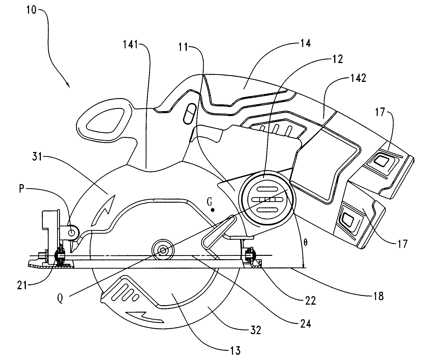
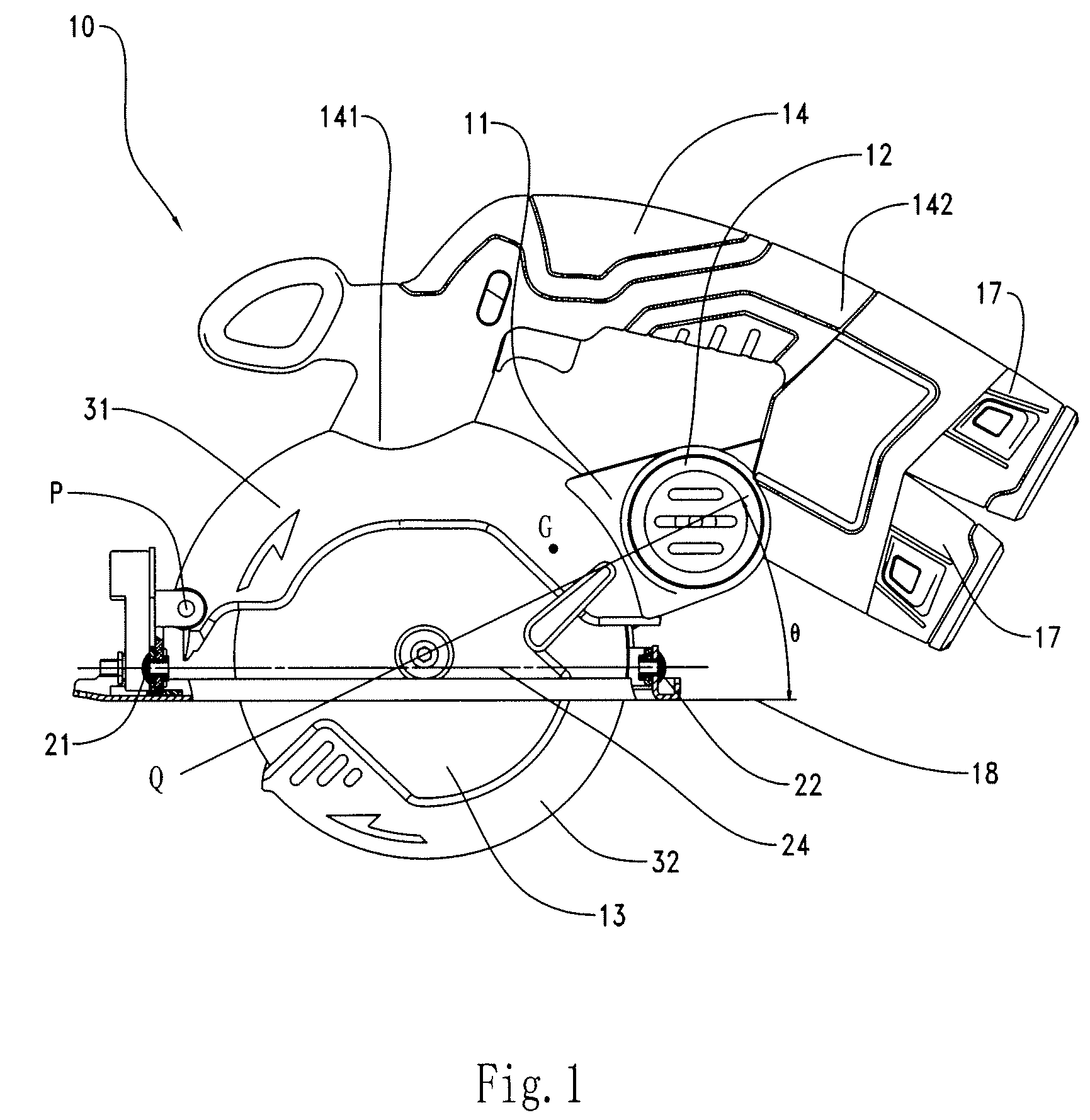
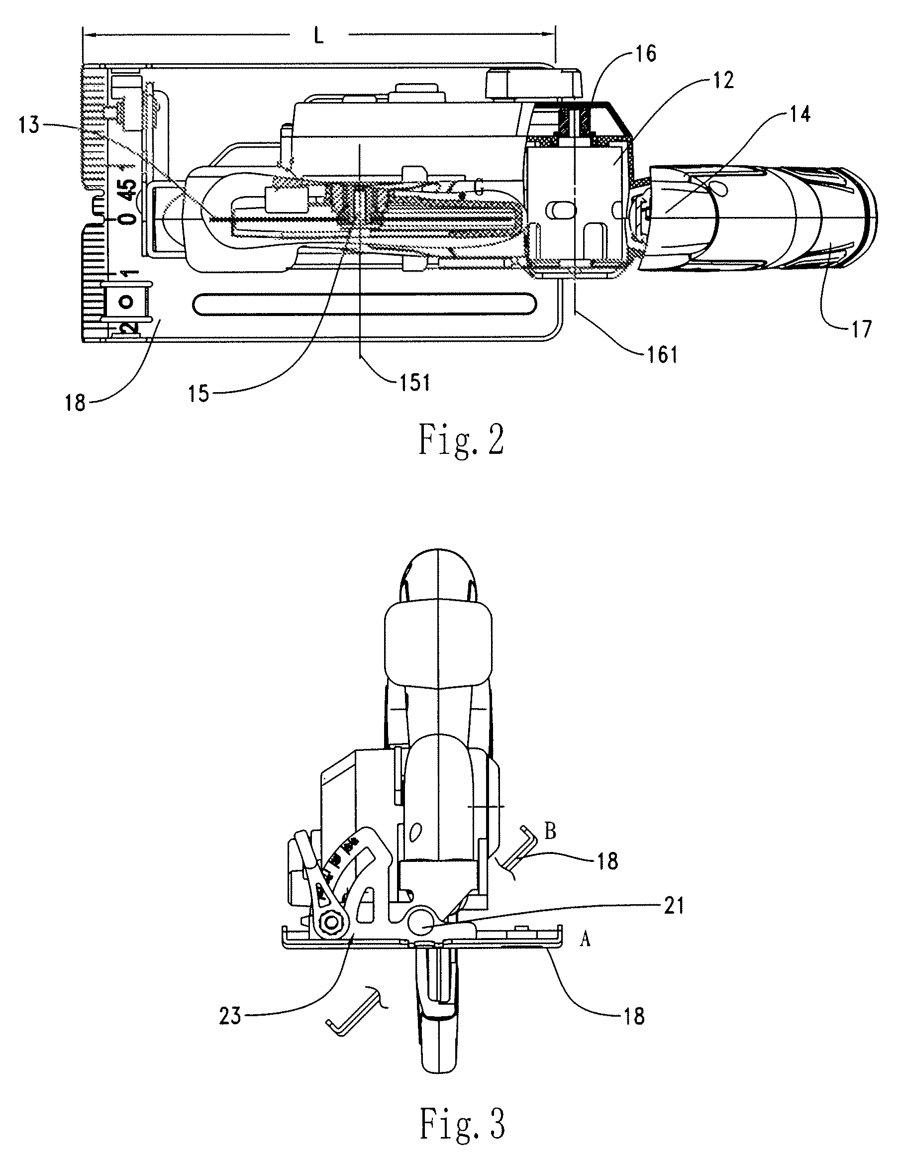
[0013]FIG. 1 illustrates a direct current circular saw 10 according to a preferred embodiment of the present invention. Referring to FIGS. 1-3, the direct current circular saw 10 comprises a housing 11, a direct current motor 12 mounted in the housing 11, a circular saw blade 13 driven to rotate by the direct current motor 12, and a handle 14 mounted or formed on the housing 11. The circular saw blade 13 is supported by a blade spindle 15 and is rotatable about an axis 151 of the blade spindle 15. The direct current motor 12 includes a motor shaft 16, and is rotatable about a rotating axis 161 of the motor shaft 16. The rotating axis 161 is parallel to the axis 151 of the blade spindle 15. A transmission device (not shown) is connected between the motor shaft 16 and the blade spindle 15 so that the rotating movement of the direct current motor 12 can be transferred to the circular saw blade 13. In the prior art, the transmission device includes gear transmission mechanisms, belt tra...


PUM

PropertyMeasurementUnit
lengthaaaaaaaaaa
gravityaaaaaaaaaa
depthaaaaaaaaaa

Abstract

A circular saw has a housing, a direct current motor, a battery assembly, a handle having first and second ends, a circular saw blade and a base plate. The motor is located outside of an area defined by the radius of the circular blade and between the first and second ends of the handle and the blade is laterally aligned with the handle. The circular saw also has a center of gravity which lies close to the plane defined by the saw blade, is below the handle and is within the length of the base plate. As a result of this arrangement, the circular saw of the present invention reduces the influence of the torque created during a cutting operation and improves the balance and operation of the circular saw.

Description

CROSS-REFERENCE TO RELATED APPLICATIONS[0001]This application claims priority under 35 U.S.C. §119 to CN 200920046200.5 filed Jun. 1, 2009, which is hereby incorporated by reference.FEDERALLY SPONSORED RESEARCH OR DEVELOPMENT[0002]Not Applicable.TECHNICAL FIELD[0003]The invention relates to a direct current circular saw having a battery assembly as a power supply. Specifically, the invention is directed to a circular saw with a direct current power supply that has improved balance and operabilityBACKGROUND OF THE INVENTION[0004]Traditionally, a portable circular saw has a housing, a motor in the housing, a handle mounted on the housing, a rotatable circular saw blade connected with the motor, a fixed blade guard mounted on the housing and covering the upper part of the blade, a base plate for supporting the housing, a movable blade guard pivotally mounted to the housing and covering the lower part of the blade which extends out of the base plate, and a battery assembly connected to ...

Claims


Application Information

Patent Timeline
Patent Type & Authority Patents(United States)
IPC IPC(8): B23D45/16
CPCB25F5/02B27B9/00
Inventor FUKINUKI, MASATOSHI
Owner CHERVON HK LTD WANCHAI
Why Eureka
Try Eureka