

Loading bay
a technology for loading bays and loading platforms, applied in the field of loading bays, can solve the problems of reducing investment considerably, affecting the quality of construction,
- Summary
- Abstract
- Description
- Claims
- Application Information
AI Technical Summary
Benefits of technology
Problems solved by technology
Method used
Image

Examples
Embodiment Construction
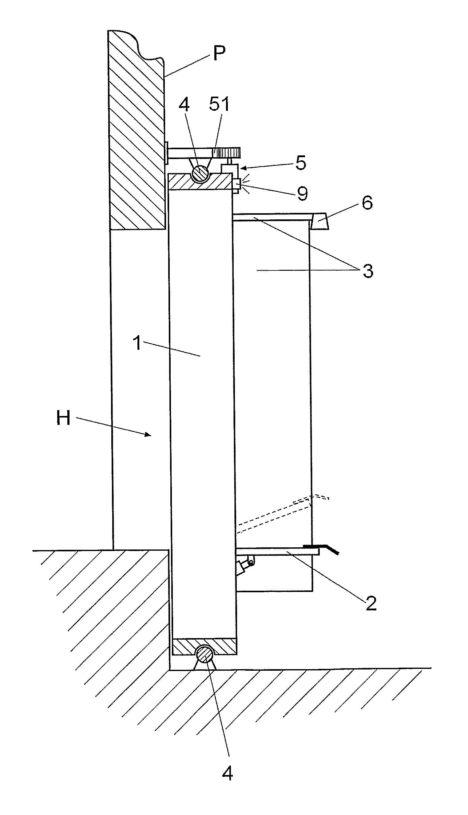
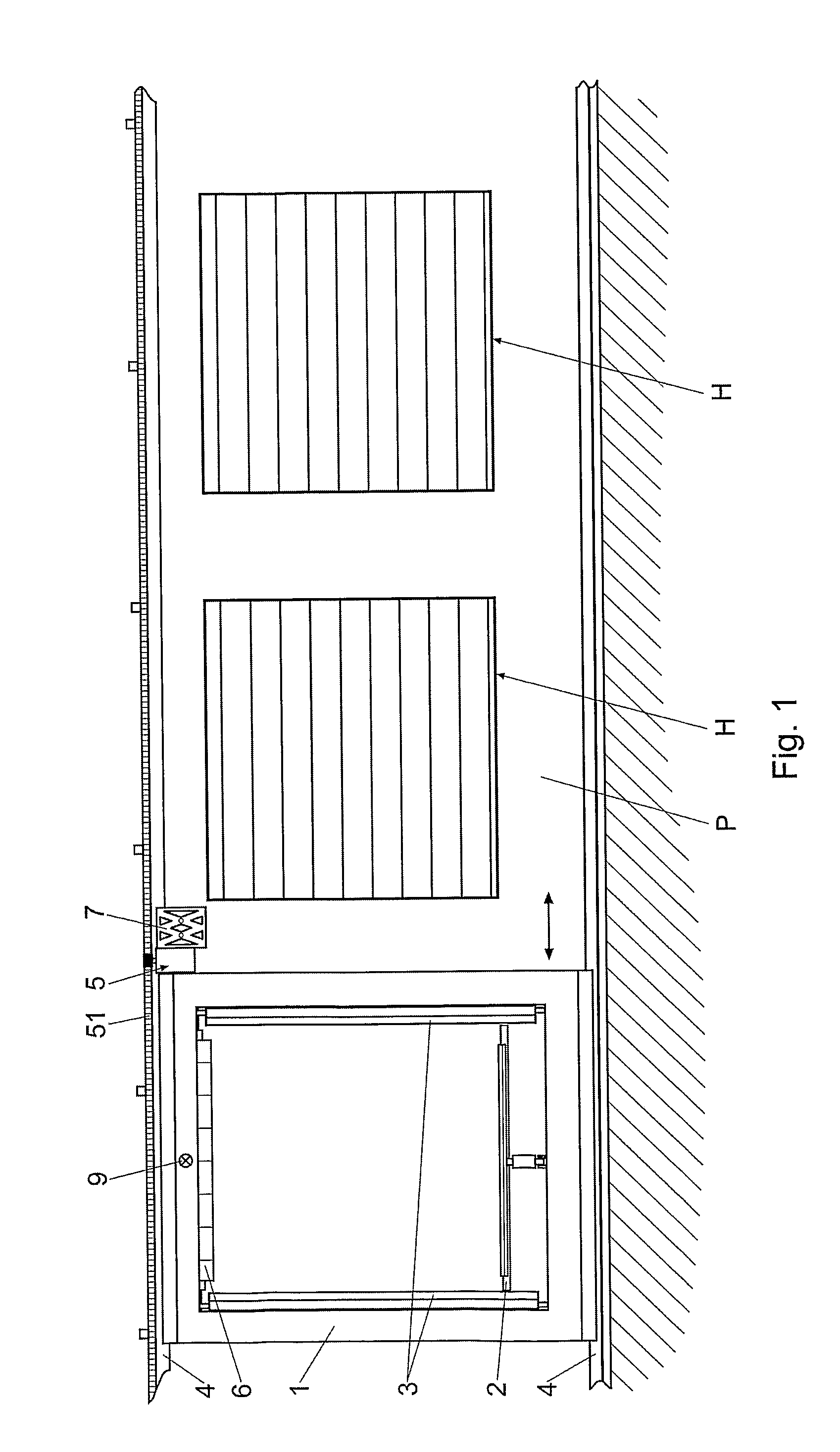
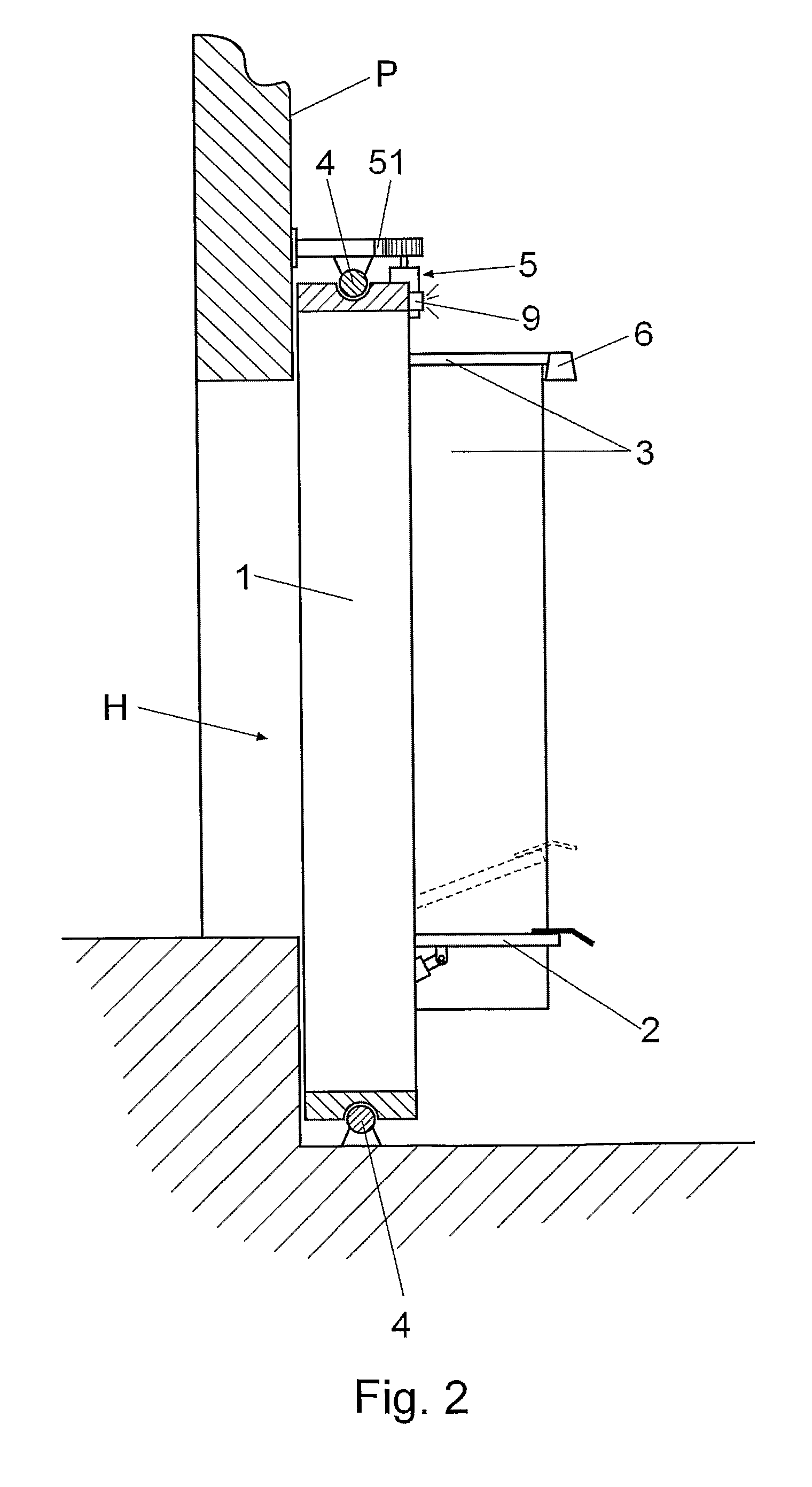
[0012]To solve the problem presented, the loading bay which is the object of this invention has been designed. It is of the type described in the aforementioned patent application PCT / ES2008 / 000770, which means that it is a loading bay that comprises a compact structure carrying at least one fold-away ramp designed to connect the shed and the truck box body, and a shelter for closing off the space between the shed and the truck box body at the side and at the top during loading and unloading operations. It presents construction specificities aimed at enabling its alternative use in different openings in the shed in question, and providing drivers, in one specific use of the invention, with adequate signaling to facilitate maneuvering while the truck approaches the opening in which the loading bay is located or, in another use of the invention, to facilitate maneuvering when the truck approaches a different opening to the one where the loading bay is positioned.
[0013]As a result, and...
PUM
 Abstract
Description
Claims
Application Information