
Pump

a technology for pumping and valves, applied in the field of pumping, can solve the problems of high production cost, high production cost, and high manufacturing cost of seat valves, and achieve the effect of saving power and improving hydraulic mechanical efficiency

Inactive Publication Date: 2013-04-23
LUK AUTOMOBILTECHN
View PDF59 Cites 1 Cited by
  • Summary
  • Abstract
  • Description
  • Claims
  • Application Information

AI Technical Summary

Benefits of technology

The present invention relates to an adjustable valve that provides cost-effective adjustment with low flow resistance and directs outgoing flow towards the intake flow. This is achieved by using a pump with a rotor and vanes that are at least radially displaceable in rotor slots, and a valve device with an elastically deformable valve tongue that makes an outgoing flow in the direction of the intake flow. In the closed state, the valve tongue assumes the contour shape on the outside of the stroke contour in the area of the outlet opening. The open valve also represents minimum flow resistance, resulting in improved pump efficiency.

Problems solved by technology

The disadvantage of this approach is the small flow cross sections that may be achieved, resulting in an excessive pressure drop; in addition, the flow around the valve seat results, for part of the volume flow, in a flow directed against the actual intake volume flow.
These flows result in losses which cause an early onset of cavitation in the intake area.
Furthermore, the manufacture of the seat valve is very complicated and is therefore expensive.

Method used


Image

  • Pump
  • Pump
  • Pump

Examples


Embodiment Construction

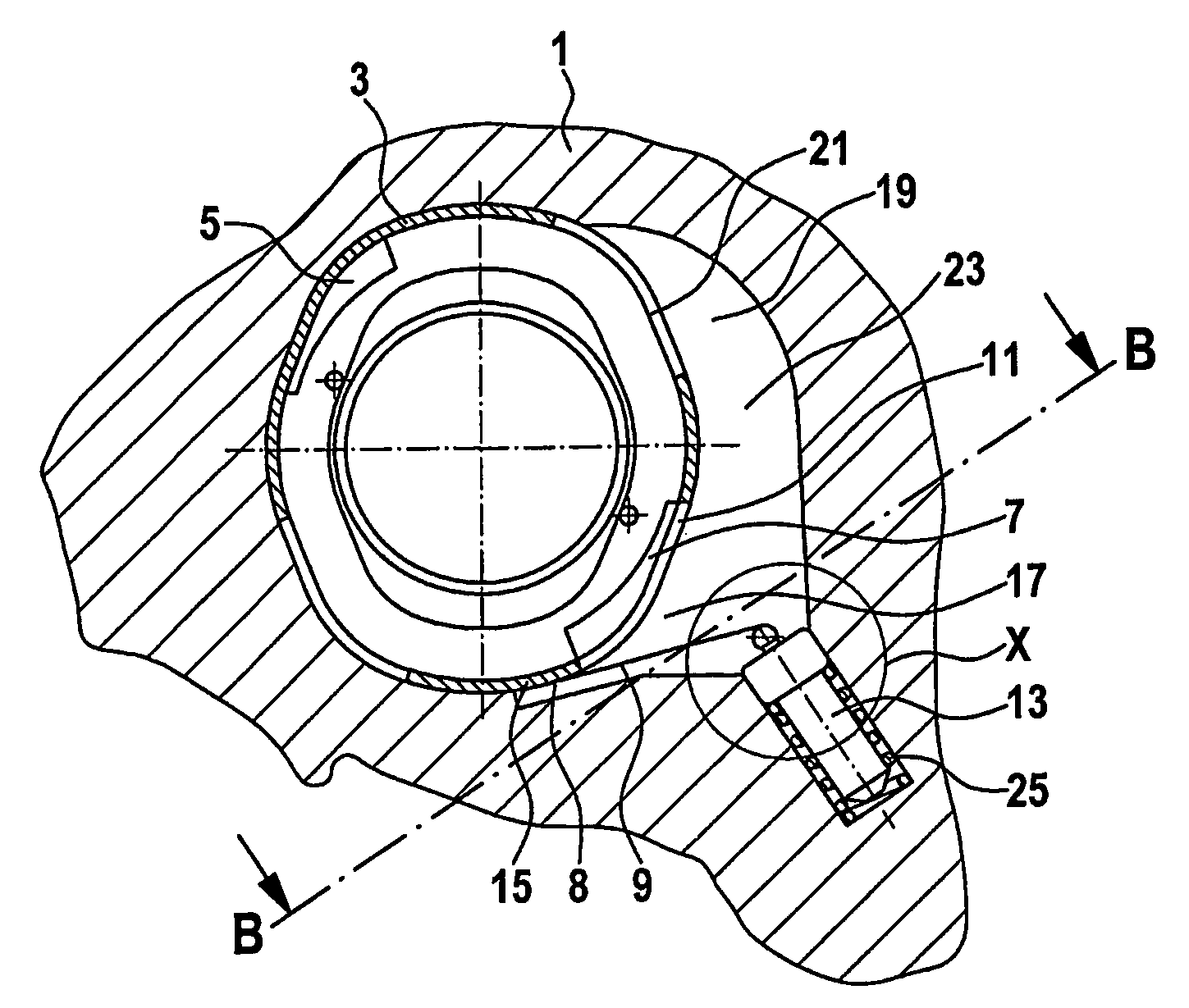
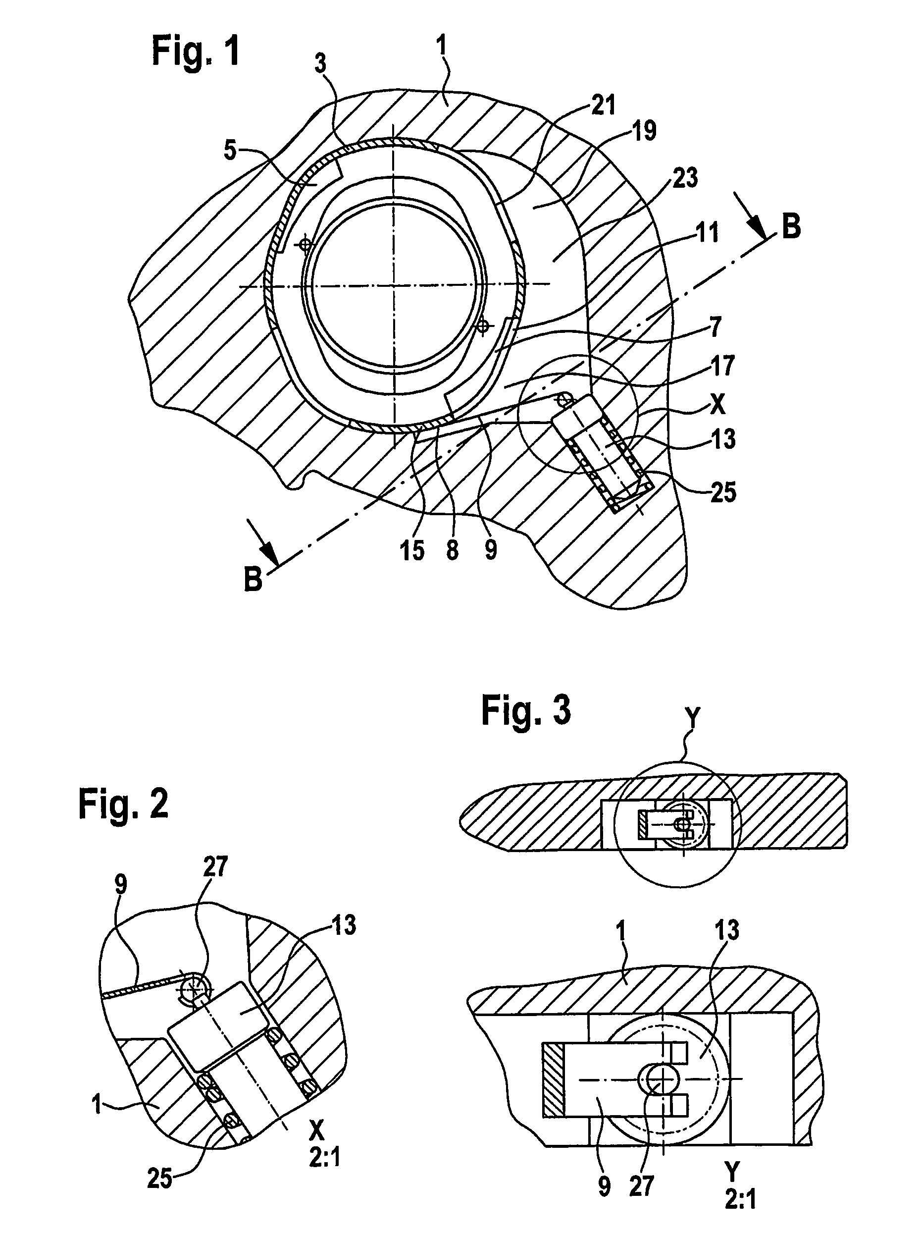
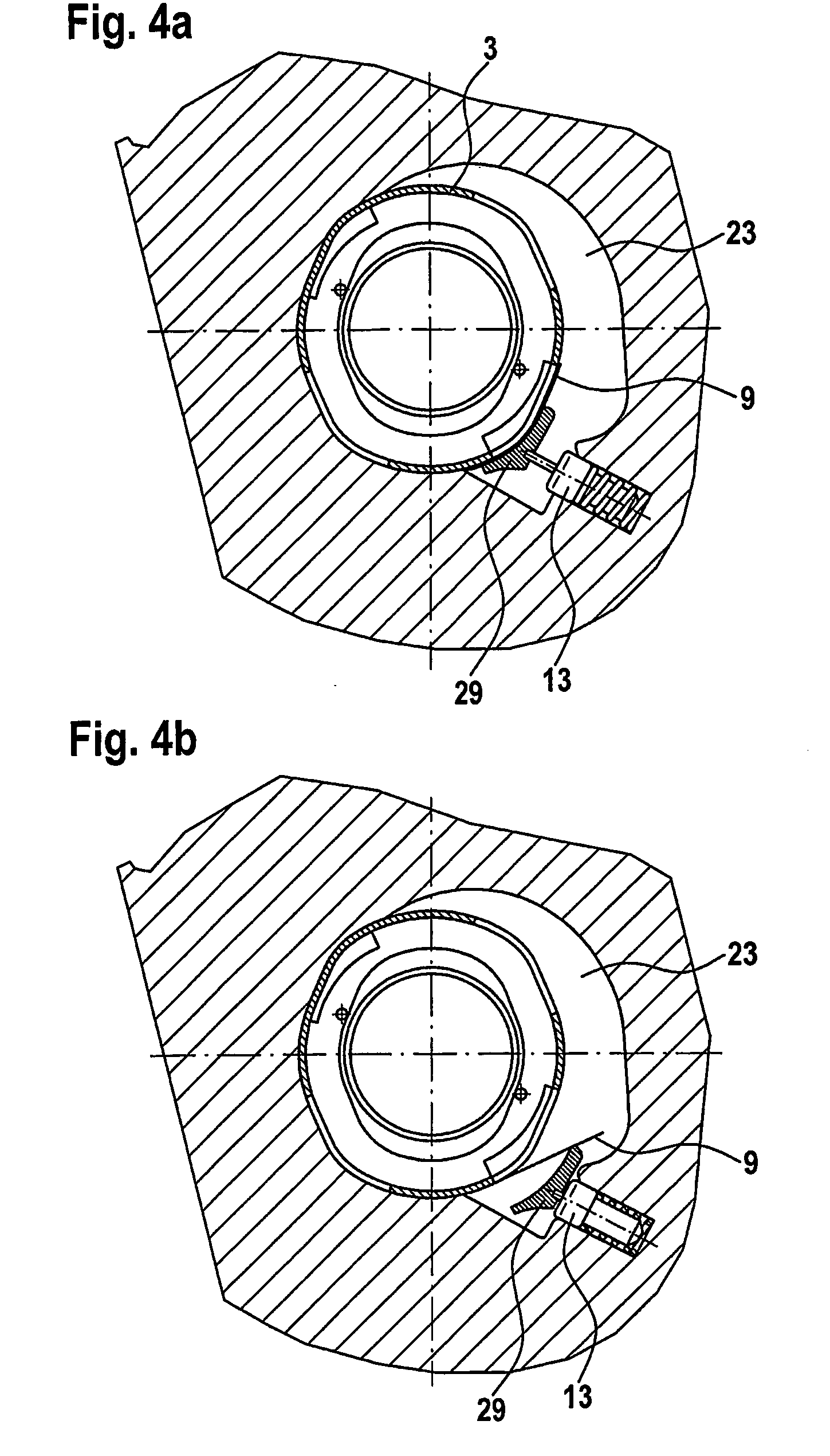
[0020]FIG. 1 shows a two-stroke vane-cell pump in cross section. A stroke contour 3 in the form of a sheet metal ring is shown in a pump housing 1. Stroke contour 3 contains a first pressure outlet 5 and a second pressure outlet 7, a spring tongue valve 8 being situated at second pressure outlet 7. In the area of second pressure outlet 7, stroke contour 3 is interrupted by a radial outlet opening 11. This outlet opening 11 is closed by valve tongue 9 when actuator 13 that is adjustable as a function of the temperature is extended and valve tongue 9 is pressed against stroke contour ring 3. Valve tongue 9 is attached to stroke contour ring 3 in area 15, so that in the open state of the tongue valve illustrated here, unimpeded flow through outlet opening 11 in flow area 17 of the pump may take place. The outflow from area 17, with valve tongue 9 functioning as a flow guide wall here, is again supplied to the actual rotation unit of the double-stroke vane-cell pump in area 19 of flow c...


PUM


Abstract

Pump, for example for pumping lubricating oil in an internal combustion engine, more particularly a multi-stroke vane cell pump, with a rotor and vanes which can slide at least radially in rotor slots and have vane heads that slide along a stroke contour, the stroke contour having a radial outlet that can be closed by a valve device.

Description

BACKGROUND[0001]The present invention relates to a pump, for example, for pumping lubricating oil of an internal combustion engine, in particular a multistroke vane-cell pump, having a rotor and vanes which are at least radially displaceable in rotor slots, whose vane heads slide along a stroke contour, the stroke contour having, among other things, a radial outlet opening, which is closeable by a valve device.[0002]Such pumps are known. Thus, for example, a multistroke vane-cell pump whose stroke contour is made of sheet metal is known. In this pump, the switchable second pumping stage is directly connected to the intake area of the first pumping stage via a radial groove in the sheet metal contour in the event of low temperature of the lubricating oil, so that at a low temperature only the first stage of the double-stroke vane-cell pump pumps. When the temperature increases, the switching stage, i.e., stage 2 of the vane-cell pump, is closed by an element which is adjustable as a ...

Claims


Application Information

Patent Timeline
IPC IPC(8): F04B49/00F16K15/16F04C2/344
CPCF04C15/064F04C2/344F04C2270/19F16K15/161
Inventor SCHULZ-ANDRES, HEIKOKAMARYS, DIRKFROWEIN, KORNELIA
Owner LUK AUTOMOBILTECHN
Learn More