Luminal structure anchoring devices and methods

a technology of anchoring device andluminal structure, which is applied in the field of devices for endoscopy or endosonographyguided transluminal interventions, can solve the problems of limited ability to manipulate needles, anchors, or other penetrating devices

Active Publication Date: 2013-04-23
BOSTON SCI SCIMED INC
View PDF259 Cites 38 Cited by
  • Summary
  • Abstract
  • Description
  • Claims
  • Application Information

AI Technical Summary

Benefits of technology

[0007]The present invention may solve the needs in the art stated above and may provide certain advantages over the prior art. The present invention solves the need for the ability to perform additional techniques by providing an apparatus capable of use in such techniques.
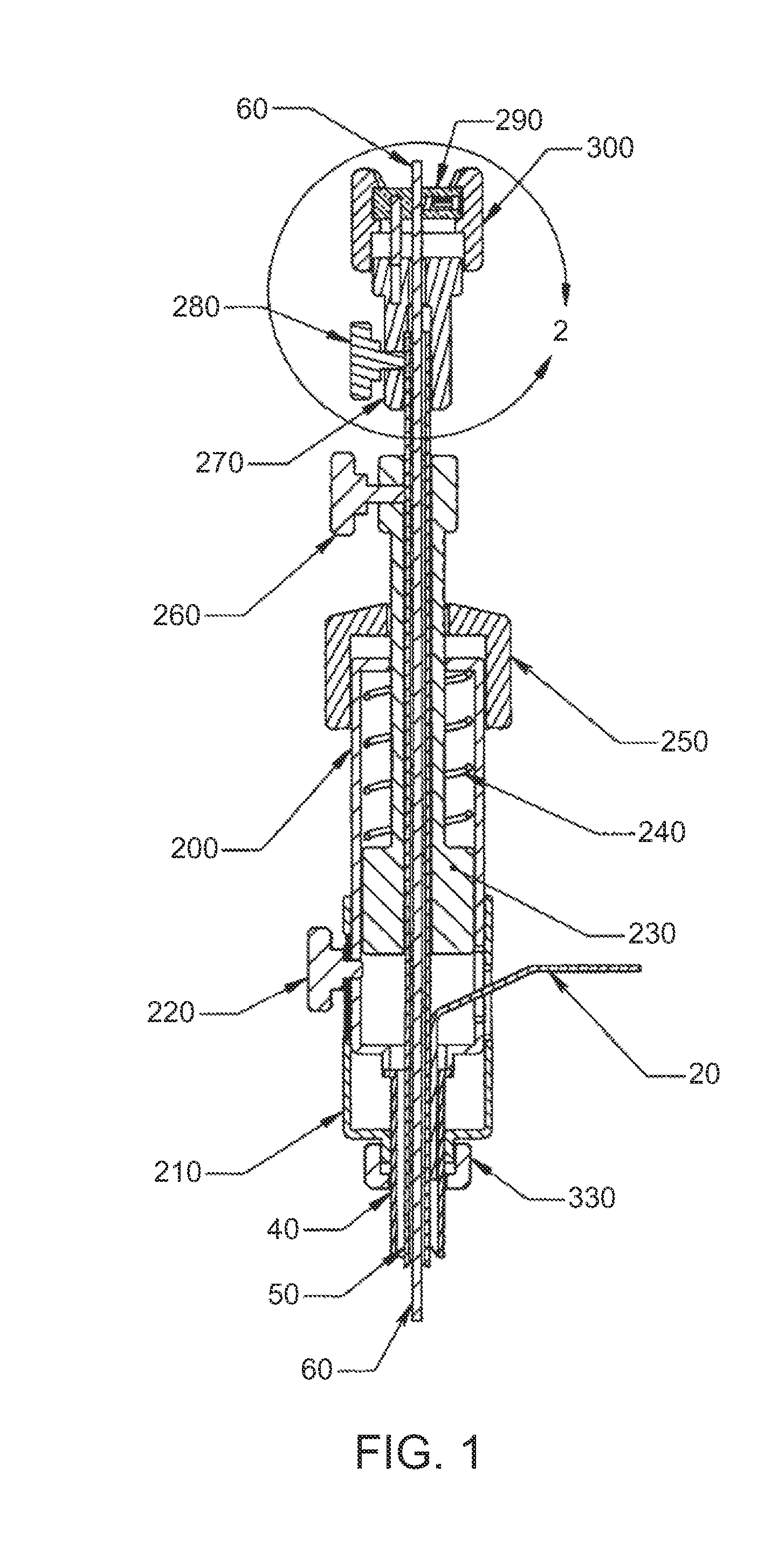
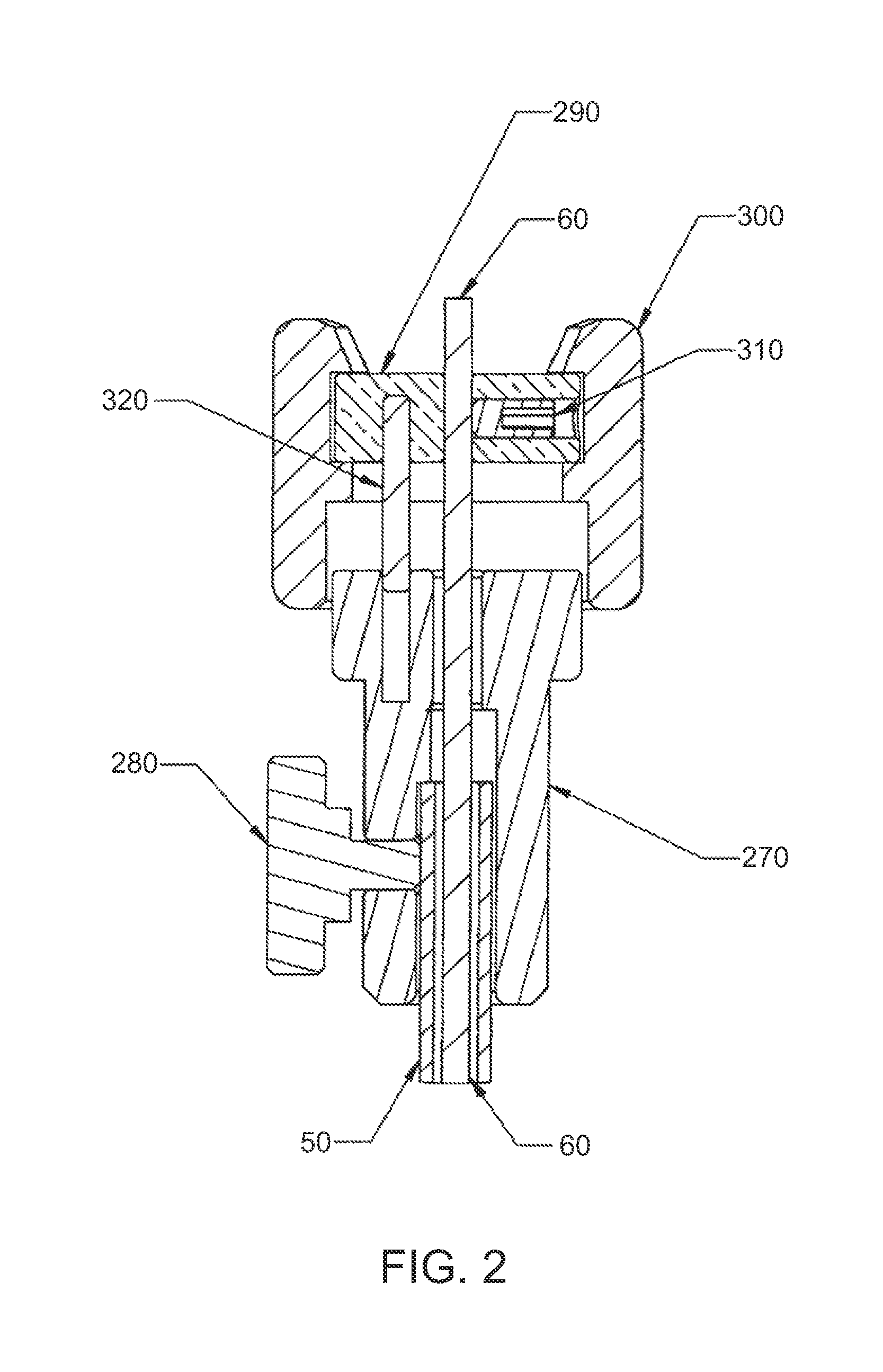
[0008]One embodiment of the present invention may be an apparatus including a roughly hollow cylindrical central member having a proximal end and a distal end; a leg member, attached to a distal end of the central member, wherein at least a portion of the leg member is adapted to permit production of an expanded distal radius in the apparatus; a tether attached to a proximal portion of the central member; an expander member, a distal portion of which is aligned co-axially through the central member; and a pusher member aligned co-axially around a proximal portion of the expander member and adapted to prevent the movement in a proximal direction of the central member.
[0011]Another embodiment of the present invention may be the apparatus described above, but further including a pre-biasing device adapted to selectively force at least a portion of the apparatus in a distal direction, and an outer sleeve surrounding the apparatus, wherein the outer sleeve is adapted to be fitted to an endoscope. The outer sleeve may be attached to the described apparatus directly or medially, or may be slidably positioned relative to the apparatus. The outer sleeve may aid the operator in directing the application of the apparatus to target tissue.
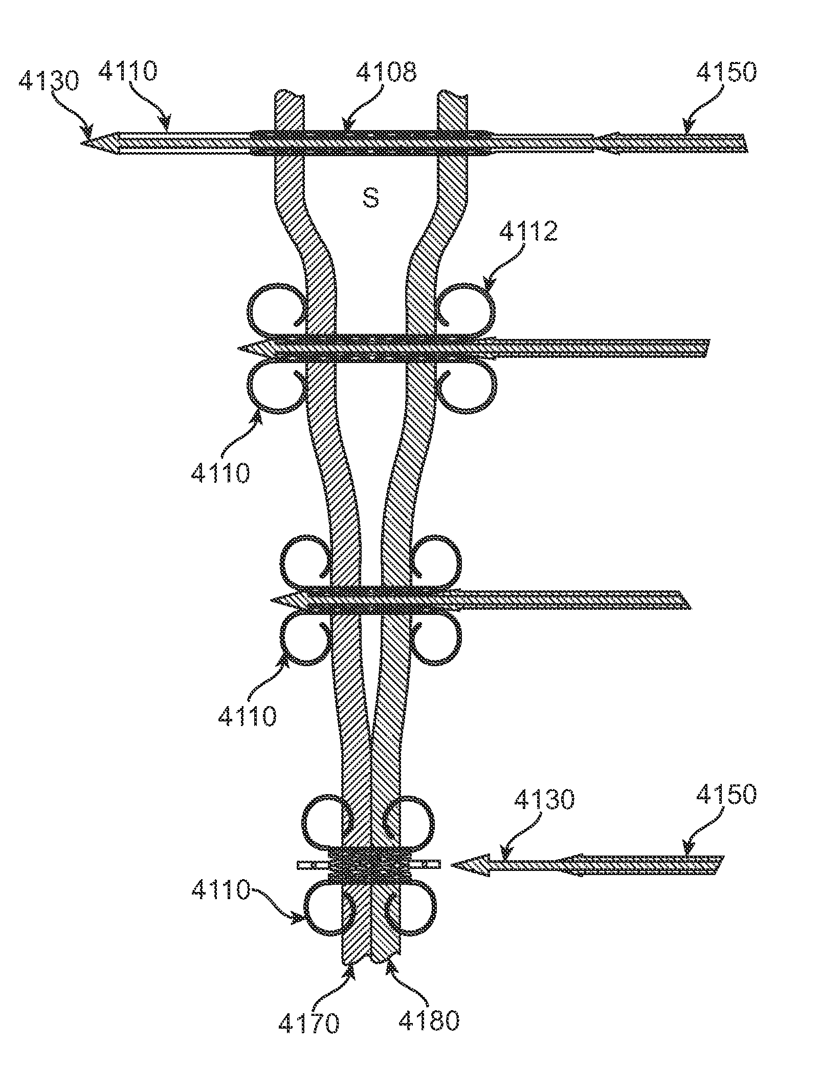
[0026]A further embodiment of the present invention may include shortening the central member as part of the approximation method described. This may be facilitated by the application of an axial compression force on the central member such that the length of the central member is shortened and the diameter of the central member is expanded. The central member may also be a stent or mesh that is comprised of two concentric hollow sections that shorten by sliding one hollow section inside the other.

Problems solved by technology

For example, in circumstances in which it is desired that an operation take place from within a luminal structure, a surgeon may have limited ability to manipulate a needle, anchor, or other penetrating device to perform procedures such as those listed above, and in particular to position tissue or to create an artificial lumen.

Method used


Image

  • Luminal structure anchoring devices and methods
  • Luminal structure anchoring devices and methods
  • Luminal structure anchoring devices and methods

Examples


Embodiment Construction

[0058]It is to be understood that the present invention is not limited to the particular methodology, compounds, materials, manufacturing techniques, uses, and applications, described herein, as these may vary. It is also to be understood that the terminology used herein is used for the purpose of describing particular embodiments only, and is not intended to limit the scope of the present invention. It must be noted that as used herein and in the appended claims, the singular forms “a,”“an,” and “the” include the plural reference unless the context clearly dictates otherwise. Thus, for example, a reference to “a suture” is a reference to one or more sutures and includes equivalents thereof known to those skilled in the art. The materials that may be used in conjunction with the present invention may include conventional materials such as stainless steel, other surgical alloys of steel, various biocompatible plastics and elastomers, and other conventional materials. In general it ma...


PUM


Abstract

A device is provided for endoscopy or endosonography- guided transluminal interventions whereby two luminal structures in the body may be drawn toward each other and a fluid conduit formed in between. The device may have a penetrating member and a hollow central member to which is coupled a distal retention member and in one embodiment a proximal retention member. The retention members may each be positioned inside one of the luminal structures and expanded from a first condition to an expanded second condition having an increased radius. The length of the central member may be shortened and its diameter expanded to approximate the two retention members and thereby the luminal structures.

Description

CLAIM OF PRIORITY[0001]This application is a continuation-in-part (CIP) of co-pending U.S. patent application Ser. No. 10 / 822,138, filed Apr. 12, 2004, entitled “Automated Transluminal Targeting Device and Anchoring Devices and Methods” which is hereby expressly incorporated by reference.FIELD OF THE INVENTION[0002]The invention relates to a device for endoscopy or endosonography-guided transluminal interventions whereby an anastomosis can be formed between two luminal structures in the body. More specifically devices and methods are described to anchor, create a fluid conduit and to approximate luminal structures using an expandable hollow stent.BACKGROUND OF THE INVENTION[0003]Endoscopy and endosonography-guided interventions have certain advantages over alternative surgical and percutaneous-guided procedures. Interventions that employ endoscopy or endosonography may avoid some of the harmful effects of alternative procedures. One technique that has been explained is a technique f...

Claims


Application Information

Patent Timeline
Patent Type & Authority Patents(United States)
IPC IPC(8): A61B17/08
CPCA61B1/041A61B17/0401A61B17/0469A61B17/1114A61B2017/00867A61B2017/0408A61B2017/0409A61B2017/0414A61B2017/0454A61B2017/0464A61B2017/1139A61B17/11A61B1/00148A61B1/0014A61N1/05A61N1/36007A61N1/3601
Inventor BINMOELLER, KENNETH F.STONE, CORBETT W.
Owner BOSTON SCI SCIMED INC
Why Eureka
Try Eureka