
Spurious DDS signal suppression

Inactive Publication Date: 2013-04-30
LOCKHEED MARTIN CORP
View PDF2 Cites 4 Cited by
  • Summary
  • Abstract
  • Description
  • Claims
  • Application Information

AI Technical Summary

Benefits of technology

The present invention is a method and apparatus for suppressing spurious DDS signals. The technical effect of this invention is that it provides a way to generate high-quality analog signals while reducing the impact of unwanted noise. This is achieved by using a combination of dithering and direct digital synthesis techniques to optimize the signal-to-noise ratio of the generated analog signals.

Problems solved by technology

These are problematic for sensor and radar applications which require sources of clean frequencies without spurious signals.
This can be the limiting factor in the performance of advanced sensor and radar systems.
Existing systems must either live with this performance impact or use complex, costly radio frequency (“RF”) circuits with limited frequency agility to generate critical source signals.
More particularly, filtering the DDS spurious energy is possible for some very limited applications—i.e., fixed, non-adjustable frequencies.
The required precision and narrowness of the needed filters is extremely challenging and greatly increases the cost of the sub-system.
These restrictions normally make this approach impractical for most applications.
High performance systems generally cannot use DDS's directly to generate critical signals.
Indirect methods are used to generate frequencies with low spurious signals but are limited by the additional circuit complexity needed to individually produce each additional frequency used by the system.

Method used


Image

  • Spurious DDS signal suppression
  • Spurious DDS signal suppression
  • Spurious DDS signal suppression

Examples


Embodiment Construction

[0019]Illustrative embodiments of the invention are described below. In the interest of clarity, not all features of an actual implementation are described in this specification. It will of course be appreciated that in the development of any such actual embodiment, numerous implementation-specific decisions must be made to achieve the developers' specific goals, such as compliance with system-related and business-related constraints, which will vary from one implementation to another. Moreover, it will be appreciated that such a development effort, even if complex and time-consuming, would be a routine undertaking for those of ordinary skill in the art having the benefit of this disclosure.

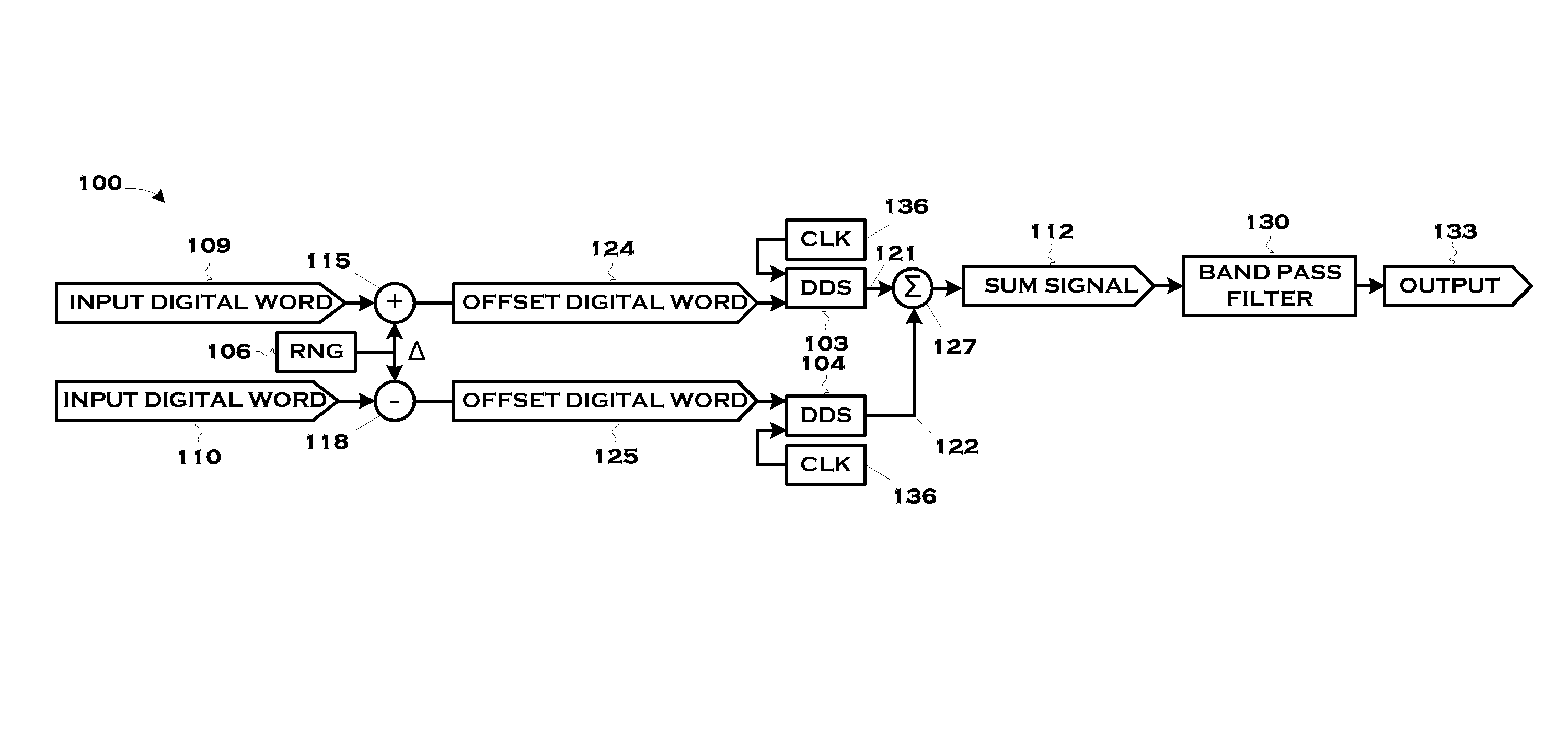
[0020]The invention uses two or more direct digital synthesizers (DDS's), each producing a random or pseudo-random, time varying, fractional portion of the final desired frequency in such a way as to spread the spurious signal energy to minimize the impact on the system performance without degrad...


PUM


Abstract

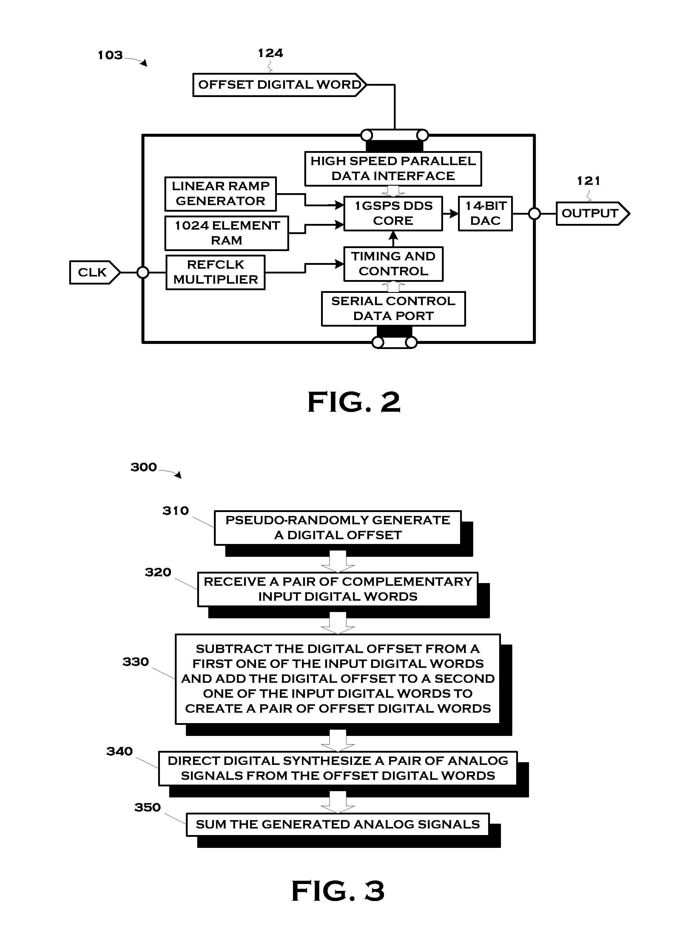
A technique for the suppression of spurious Direct Digital Synthesis (“DDS”) signals includes a method and an apparatus that equally and oppositely dithers a pair of complementary input digital words from which a pair of analog signals are direct digital synthesized and then mixes the generated analogy signals.

Description

[0001]The earlier effective filing date of co-pending U.S. Provisional Application Ser. No. 60 / 991,551, entitled, “Spurious DDS Signal Suppression”, filed Nov. 30, 2007, in the name of the inventor Dana W. Kintigh is hereby claimed for all common subject matter under 35 U.S.C. §120. This application is also hereby incorporated by reference for all purposes as if set forth verbatim herein.BACKGROUND OF THE INVENTION[0002]1. Field of the Invention[0003]The present invention pertains to applications for Direct Digital Synthesis (“DDS”), and, more particularly, the suppression of spurious DDS signals.[0004]2. Description of the Related Art[0005]Conventional DDS's generate discrete sidebands as spurious signals combined with their desired output frequency. These are problematic for sensor and radar applications which require sources of clean frequencies without spurious signals. This can be the limiting factor in the performance of advanced sensor and radar systems. Existing systems must...

Claims


Application Information

Patent Timeline
IPC IPC(8): G06F1/02
CPCG06F1/022G06F2211/902
Inventor KINTIGH, DANA W.
Owner LOCKHEED MARTIN CORP
Learn More