Harvesting corn cobs
a corn cob and corn technology, applied in the field of corn cobs harvesting, can solve the problems of crude current methods no commercially available equipment for collecting corn cobs, and insufficient cleaning methods to properly collect all
- Summary
- Abstract
- Description
- Claims
- Application Information
AI Technical Summary
Benefits of technology
Problems solved by technology
Method used
Image
Examples
first embodiment
[0113]The following description of further embodiments of the invention discloses elements and features which may also be used in the first embodiment described above.
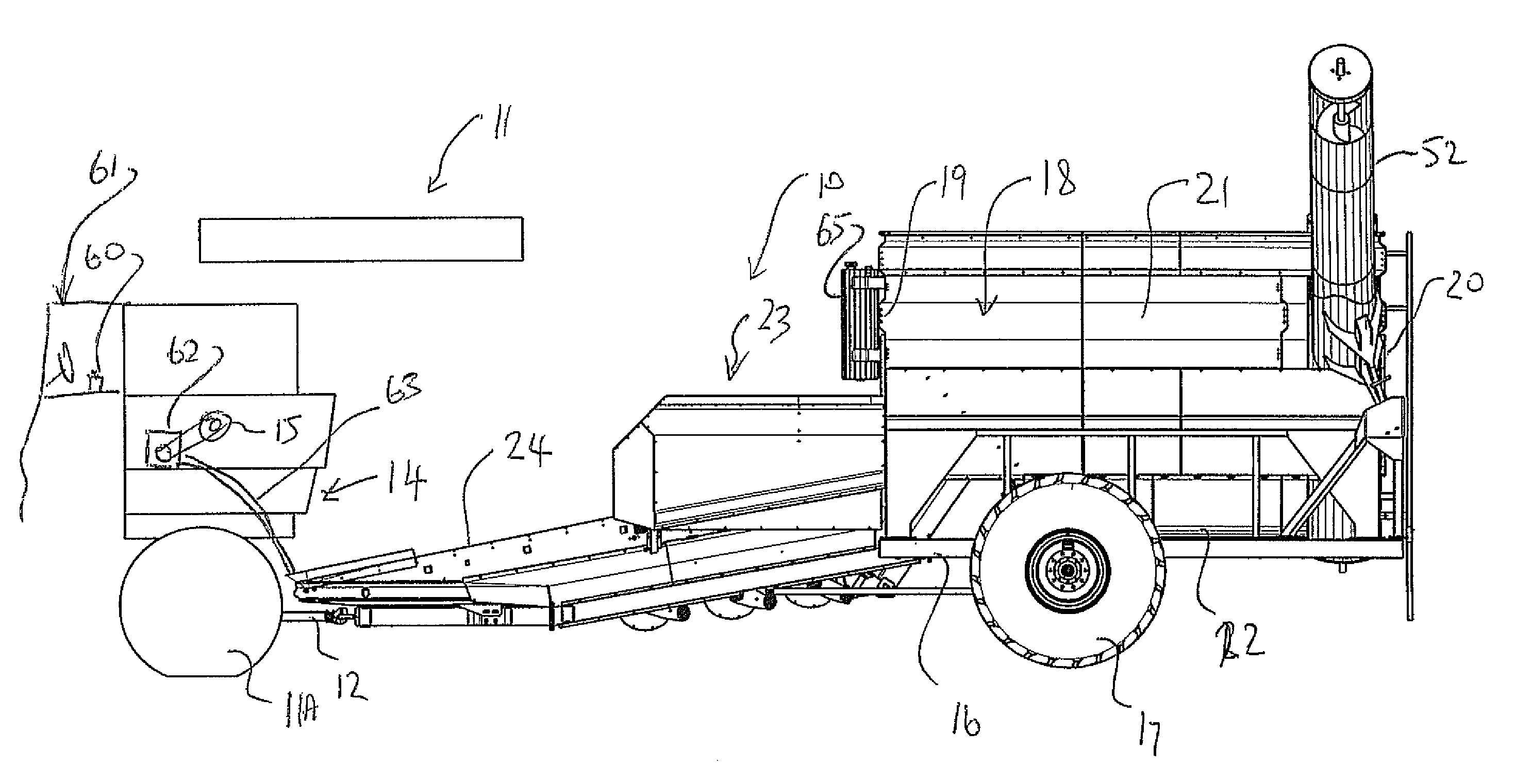
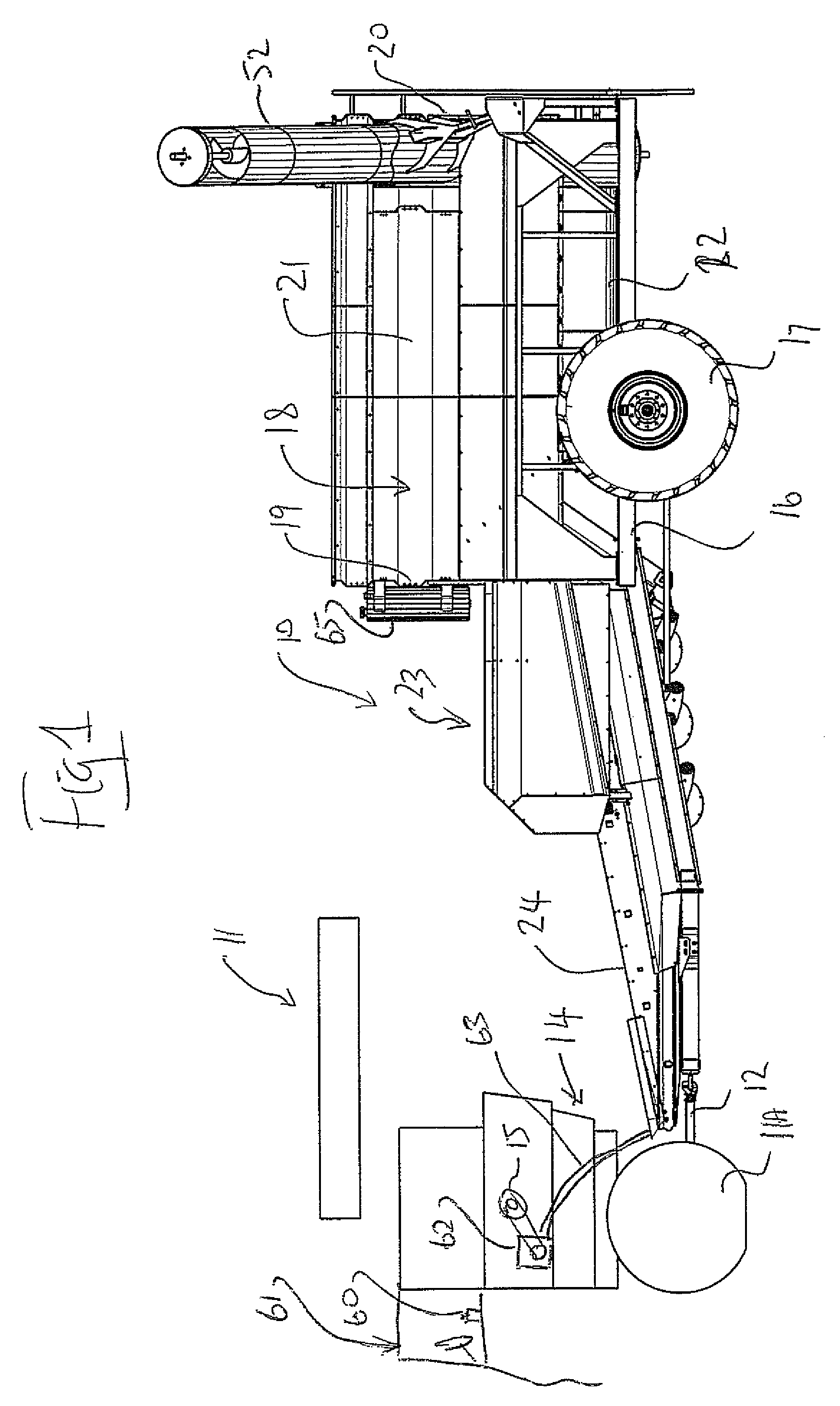
[0114]Referring to FIGS. 14 and 15, a corn cob harvesting machine 110 is pulled behind the rear end of a typical combine 111. The combine 111 is equipped with a specialized hitch 112 to quickly disconnect the cob harvesting machine, as it is a common practice to switch between harvesting corn and soybean on a daily basis dependant on the weather. The cob harvester is powered hydraulically by a drive system 113 taking power from combine's chopper drive.
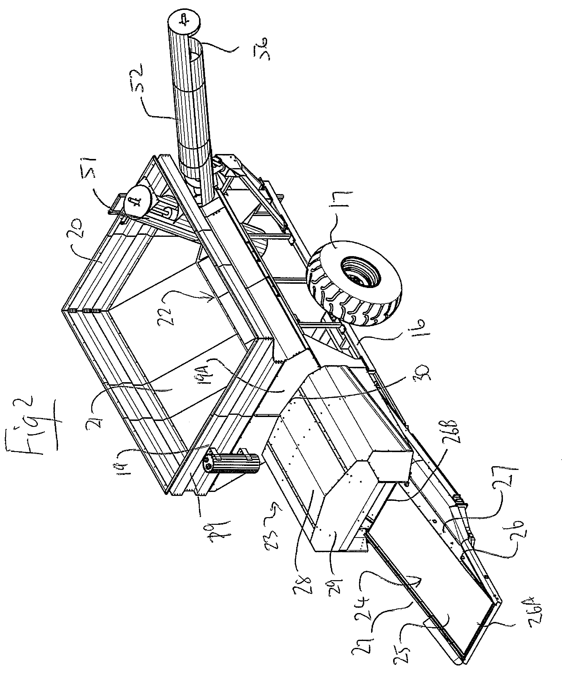
[0115]The corn cob harvester includes an inlet conveyor 120 that has a feed hopper 121 placed under the combine's residue outlet 114. It is preferable that the residue from the sieves 115 as well as the walkers or rotors 116 (depending on combine type) be combined in the inlet conveyor's hopper to capture all possible cobs.
[0116]The inlet conveyor 120 elevates the residue...
third embodiment
[0126]Referring now to the third embodiment shown in FIG. 21, a corncob harvesting machine 210 of the same general type as that disclosed above is pulled behind the rear end of the combine 211. The combine is equipped with a specialized hitch 212 of the arrangement previously described to quickly disconnect the cob harvesting machine. The cob harvester is powered hydraulically by a drive system (not shown) taking a drive outlet from the combine's chopper drive, again as previously described.
[0127]The corn cob harvester includes the inlet conveyor 220 that has its feed hopper 221 placed under the combine's residue outlet 214. It is preferable that the residue from the sieves as well as the walkers or rotors (depending on combine type) be collected in the inlet conveyor's hopper in order to capture all possible cobs.
[0128]The inlet conveyor elevates the residue and drops the stover into a cob separating region 280. The cob separating mechanism includes a fan 281 for generating air jet...
second embodiment
[0141]The cob separating mechanisms for the second and third stages is similar to that of the second embodiment except that each includes only a single air plenum. Thus these separating devices include the fan 381 for generating air flow and pressure, ducts 334 for transporting pressurized air to transverse air plenums 335 and 336 and holes in the plenums for creating air jets 337 to blast through the stover. Each plenum's air jet velocity is adjusted independently with control valves 141 and the jet's trajectory is altered with rotational adjustment of the plenum about its transverse axis. The cobs and residue fall from the upper end of the first conveyor 320 though the open space to the inlet 310 at the bottom end of the second conveyor 310 and pass through a hard air blast from air plenum 335. The air blast accelerates and lifts the lighter residue separating it from the heavier cobs. The lighter residue is directed into fins 138 mounted to the bottom side of the second stage cov...
PUM
 Abstract
Description
Claims
Application Information
 - R&D
- Intellectual Property
- Life Sciences
- Materials
- Tech Scout
- Unparalleled Data Quality
- Higher Quality Content
- 60% Fewer Hallucinations
Browse by: Latest US Patents, China's latest patents, Technical Efficacy Thesaurus, Application Domain, Technology Topic, Popular Technical Reports.
© 2025 PatSnap. All rights reserved.Legal|Privacy policy|Modern Slavery Act Transparency Statement|Sitemap|About US| Contact US: help@patsnap.com


