Support structures on roofs

a technology for supporting structures and roofs, applied in roof drainage, skylights/domes, building repairs, etc., can solve the problems of high level of stress on joints, leakage of water around the perimeter of conventional roof curbs, and all known conventional structures have a tendency to leak water, so as to reduce the number of incidents of water leakage, especially leakage about the mounting structure, and simplify the effect of joining

Active Publication Date: 2013-05-14
T&M INVENTIONS
View PDF57 Cites 36 Cited by
  • Summary
  • Abstract
  • Description
  • Claims
  • Application Information

AI Technical Summary

Benefits of technology

[0019]The invention provides a curbless construction system for installing roof load supports such as roof closure structures, optionally skylights and / or smoke vents, optionally including two or more such roof closure structures in end-to-end relationship, onto the major rib elevations of a building's metal roof panel system, thereby utilizing the beam strength of the roof rib elevations on the surface of the roof, as the support for such loads. Where skylight assemblies are placed in end-to-end relationship over a common roof aperture, the upper diverter and lower closure at the facing ends of such skylight assemblies are replaced with male and female mating strips, thus to simplify such joinder while providing substantial barrier to water leakage at the abutting ends of the adjacent skylight assemblies. Numerous roof structures include such ribs and rib elevations, sometimes deemed “ribs” or “corrugations”, including the standing seam, snap seam and “R” panel roof types. The roof support and / or closure structures of the invention are fastened to the rib structures of the metal roof panels above the water line. By mounting the loads above the water line, the number of incidents of water leaks, especially leaks about the mounting structure, is greatly reduced. By mounting the loads on the roof panels, themselves, the supported loads, such as skylights or vents, can move with the respective roof panels as the roof panels expand and contract.
[0021]In addition, the invention further improves control of water leakage and condensation formation inside the climate-controlled building envelope. Water leakage is reduced by re-designing the upper diverter and the lower closure, and providing for a second installation step, and by providing a male / female intermediate joint where skylight assemblies meet end to end intermediate the length of the roof aperture. Condensation is reduced by lifting the insulation inside the building to cover the sides of the closure support structure and providing a no-fastener securement of the insulation at an upper location in the closure support structure, and by providing thermally insulating materials as barriers to penetrating portions of fasteners, penetrating from outside the climate controlled building envelope, preventing such fasteners from entering the climate-controlled building envelope.

Problems solved by technology

Fitting skylight assemblies into such roof aperture, in a separately-mounted roof structure, presents problems.
All known conventional structures have a tendency to leak water when subjected to rain.
One of the causes of roof leaks around the perimeter of conventional roof curbs which attach primarily through the panel flat at the water line are due to foot traffic, such as heel loads or other dynamic loads imposed by workers wheeling gas cylinders or other heavy equipment on the roof panel e.g. with dollies.
This type of dynamic loading can cause high levels of stress on the joints that rely solely on mastic to provide seals in the wet areas, namely in the panel flats.
Such leaks are common around fastener locations as the panels flex under load and cause the sealant to deform, such that in time passages develop through the sealant, which allows for the flow of water through such passages.
In addition, conventional curb-mounted skylights tend to accumulate condensation, especially about fasteners which extend from the outside of the building to the inside of the climate-controlled building envelope.

Method used


Image

  • Support structures on roofs
  • Support structures on roofs
  • Support structures on roofs

Examples


Embodiment Construction

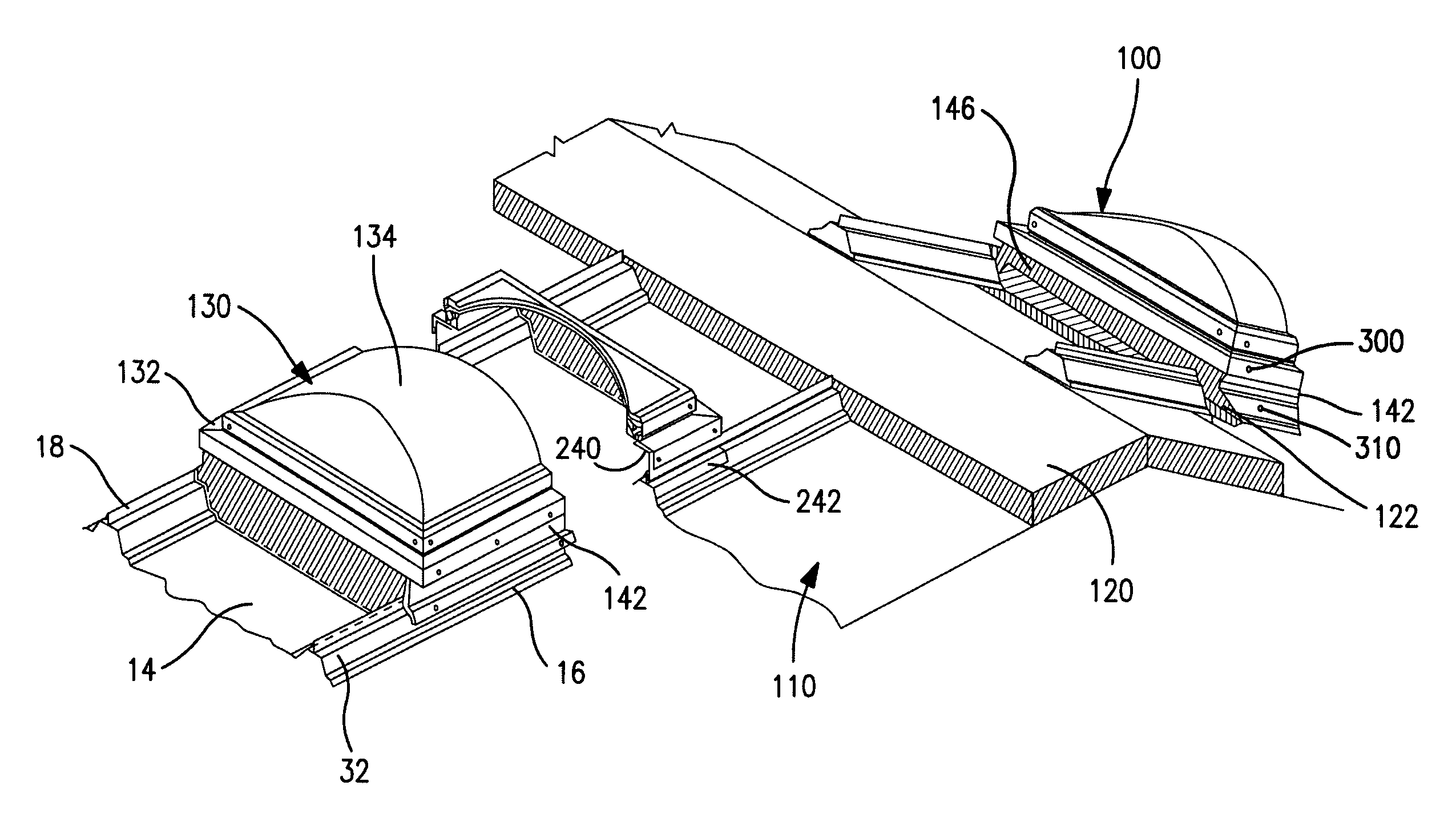
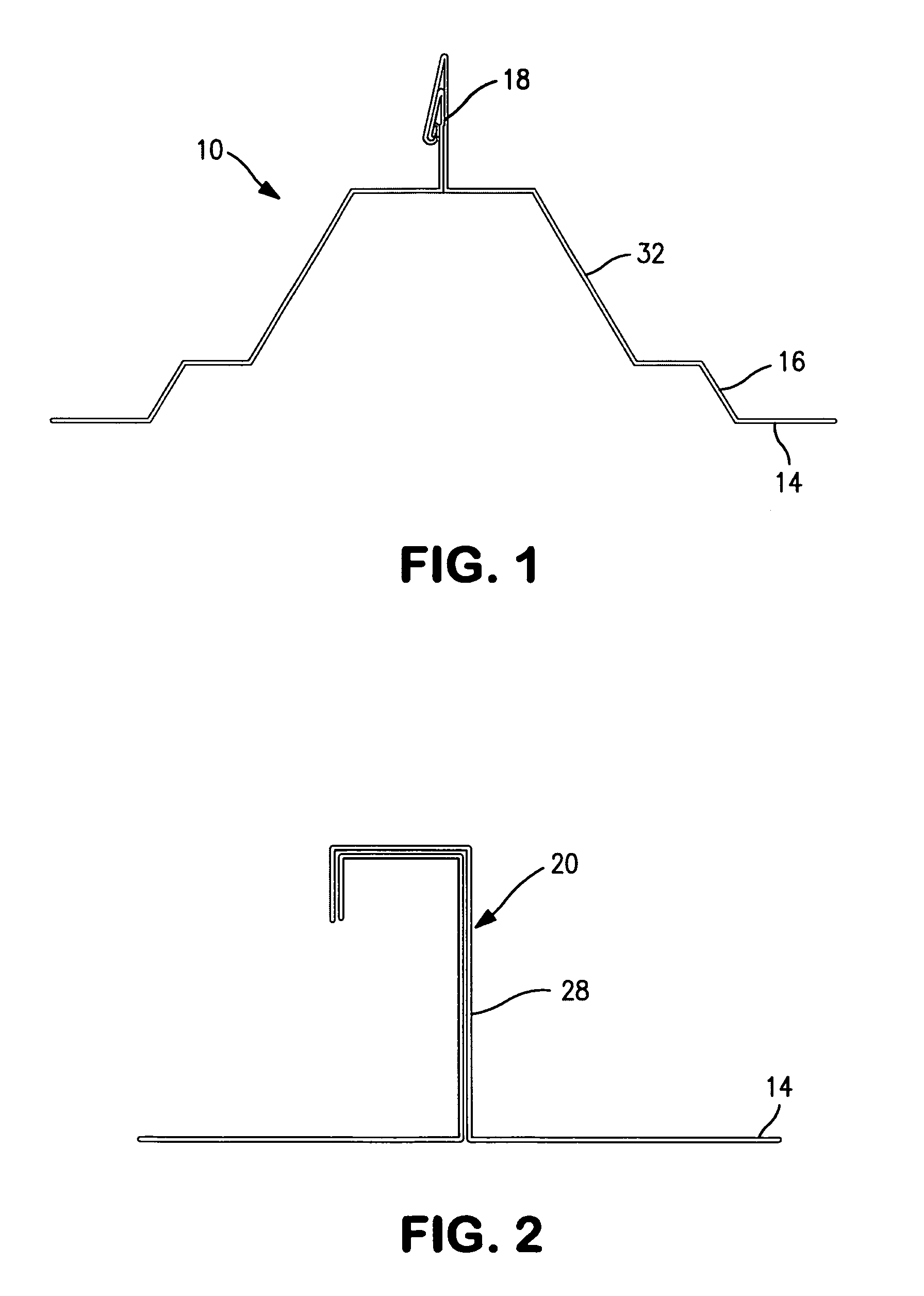
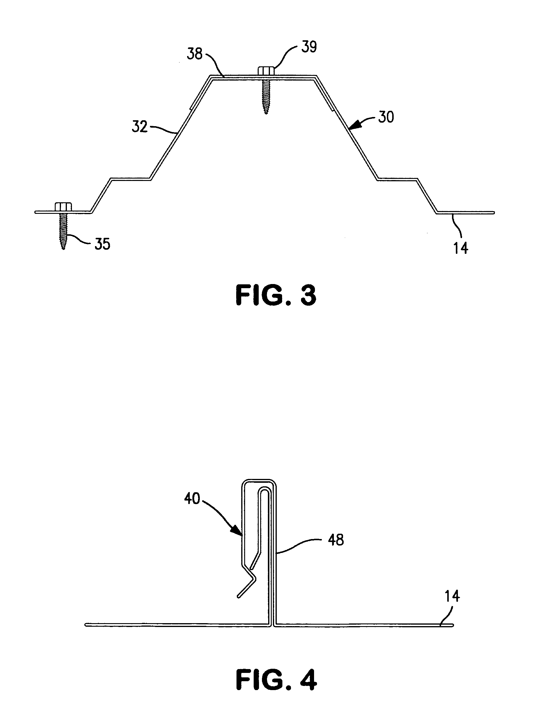
[0072]The products and methods of the present invention provide a load support structure, for use in installing various exterior roof loads, including structures which close off apertures in metal roofs. For purposes of simplicity, “closure support structure” will be used interchangeably to mean various forms of closed-perimeter structures which are mounted on ribs of raised elevation metal roof structures, including across the flat of a roof panel, and which collectively define an upstanding enclosing wall which defines a surrounded space about an aperture in a roof, and supports either a closure over the aperture, or a conduit which extends through the roof aperture. Skylight assemblies and smoke vents are non-limiting examples of closures over such roof apertures. Air handling operations such as vents, air intake, and air or other gaseous exchange to and / or from the interior of the building are non-limiting examples of operations where conduits extend through the roof aperture. I...


PUM


Abstract

Roof load supports support e.g. skylights and / or smoke vents, optionally including two or more closures in end-to-end relationship, from ribs of a metal roof. Where skylights are end-to-end over an aperture, mating strips support the skylights between upper and lower ends of the support structure. Supports of the invention are mounted above the water line whereby the number of water leaks about the mounting structure is greatly reduced. Water leakage is further reduced by re-designing the upper diverter and the lower closure, and providing for a second installation step. Condensation is further reduced by lifting the insulation inside the building to cover the sides of the closure support structure and providing a no-fastener securement of the insulation at an upper location in the closure support structure, and by providing thermally insulating materials as barriers to penetrating portions of fasteners, penetrating from outside the climate controlled building envelope.

Description

CROSS-REFERENCE TO RELATED APPLICATION[0001]This application is a Continuation-In-Part application which claims priority under 23 U.S.C. §120 to application Ser. No. 13 / 065,172, filed Mar. 14, 2011.BACKGROUND OF THE INVENTION[0002]Various systems are known for supporting loads on roofs, and for installing skylights and / or smoke vents into roofs.[0003]Commonly used skylighting systems have translucent or transparent closure members, also known as lenses, mounted on a support structure which extends through an aperture in the roof and is mounted to building support members inside the building. Ambient daylight passes through the lens and thence through the roof aperture and into the building.[0004]Thus, conventional skylight and smoke vent installations use a complex structure beneath the exterior roofing panels and inside the building enclosure, in order to support a curb which extends through the roof and supports the skylight lens. Conventional skylight curbs, thus, are generally i...

Claims


Application Information

Patent Timeline
Patent Type & Authority Patents(United States)
IPC IPC(8): E04B7/18E04B7/02E04B7/04E06B3/26
CPCE04D13/032E04D13/0305E04D13/04E04D13/031E04D13/0315E04D13/0404E04D13/03E04D3/30E04D13/1475E04B7/02E04B7/18E04D13/0481E04B2103/06E04D2013/0486
Inventor MCLAIN, MICHAEL J.PENDLEY, TIMOTHY
Owner T&M INVENTIONS
Why Eureka
Try Eureka