Mobile communication device

a communication device and mobile technology, applied in the direction of antennas, antenna details, antenna earthings, etc., can solve the problems of increasing additional research and development costs and undesirable increase in r&d costs, and achieve the effect of relieving the

Active Publication Date: 2013-05-14
ACER INC
View PDF10 Cites 0 Cited by
  • Summary
  • Abstract
  • Description
  • Claims
  • Application Information

AI Technical Summary

Benefits of technology

[0006]The mobile communication device according to the present invention comprises a dielectric substrate, a first ground plane, an antenna element, a second ground plane and an equivalent band-stop circuit. The first ground plane may be the ground plane of a main board in a folder-type mobile phone, formed on the dielectric substrate by etching or printing. The antenna element is disposed on or nearby the dielectric substrate and is electrically connected to a signal source located on the dielectric substrate. The second ground plane may be the ground plane of an upper board in the folder-type mobile phone, and is disposed in close proximity to one edge of the first ground plane and electrically connected to the first ground plane through a metal strip. The equivalent band-stop circuit may be disposed on the first ground plane or the second ground plane, comprising a slit whose open end being close to the metal strip, and a capacitive element mounted across the slit, with two ends of which capacitive element being electrically connected to two sides of the slit, respectively. The surface current distribution along the perimeter of the slit is in general very strong between the first ground plane and the second ground plane, so the slit is allowed to provide an equivalent feature of distributive inductance. The capacitive element is mounted across the two sides of the slit, and the capacitance value (C) provided thereby and the equivalent inductance value (L) provided by the slit can together form a parallel resonance at a specific frequency, thus enabling the band-stop effect, so such a feature can be equivalent to an equivalent band-stop circuit configured between the first ground plane and the second ground plane.
[0007]In such a case, the surface current distribution of the second ground plane excited by the antenna element can be significantly reduced, thereby greatly relieving the effect imposed by the second ground plane upon the performances of the antenna element.

Problems solved by technology

Taking the folder-type mobile phone as an example, compared to the bar-type mobile phone, the system ground plane thereof is formed by the upper-board ground plane and the main-board ground plane; therefore, if the antenna in the bar-type mobile phone is directly applied to the folder-type mobile phone, the antenna needs to be adjusted or re-designed, which may increase additional research and development costs.
For example, the U.S. Pat. No. 6,750,821 B2, entitled “Folded Dual-Band Antenna Apparatus” discloses an antenna design applied in the bar-type mobile phone; however, if such an antenna is directly applied in a folder-type mobile phone, it is required to adjust the antenna parameters, causing undesirable increase in R&D costs.

Method used


Image

  • Mobile communication device
  • Mobile communication device
  • Mobile communication device

Examples


Embodiment Construction

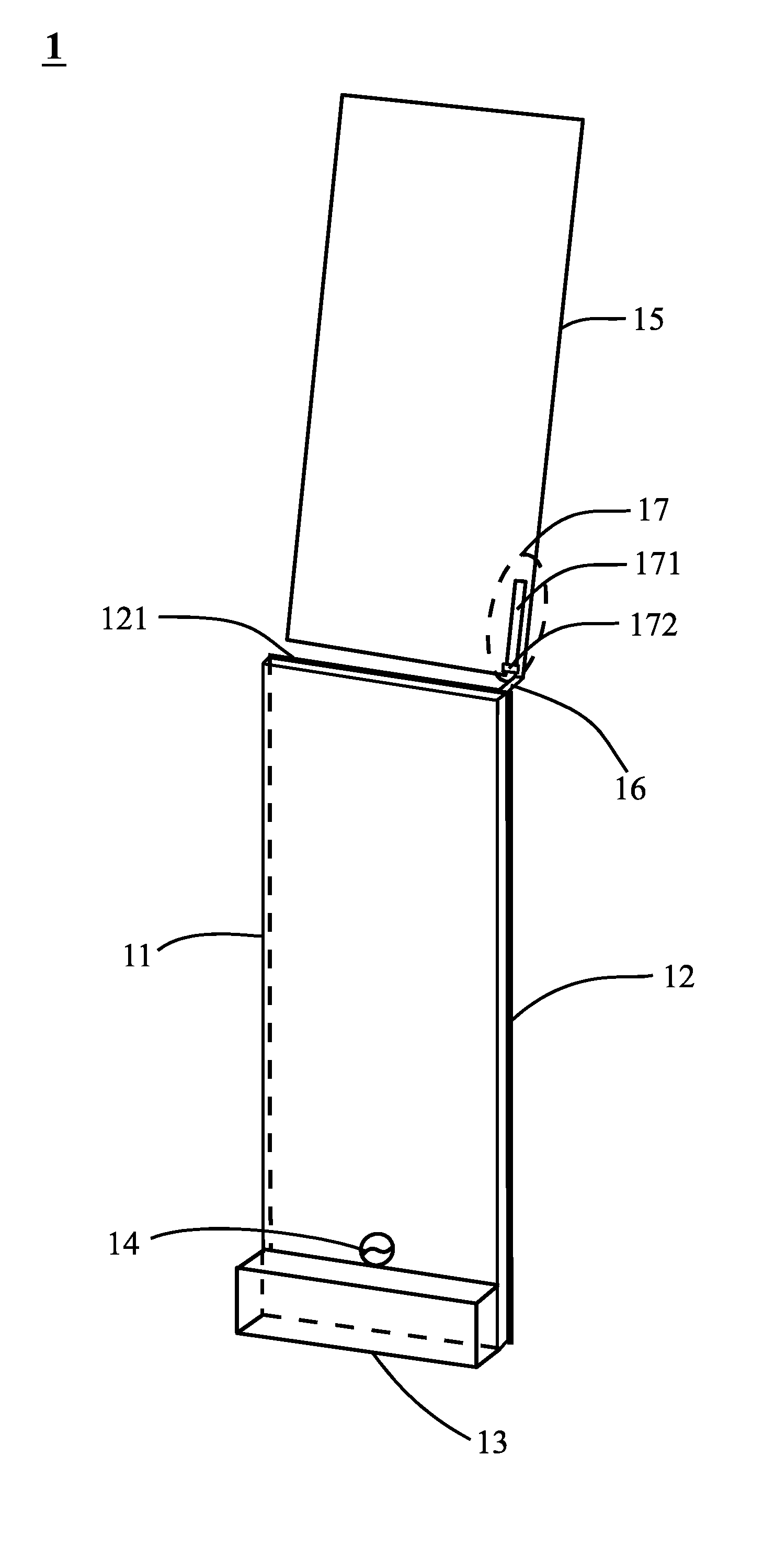
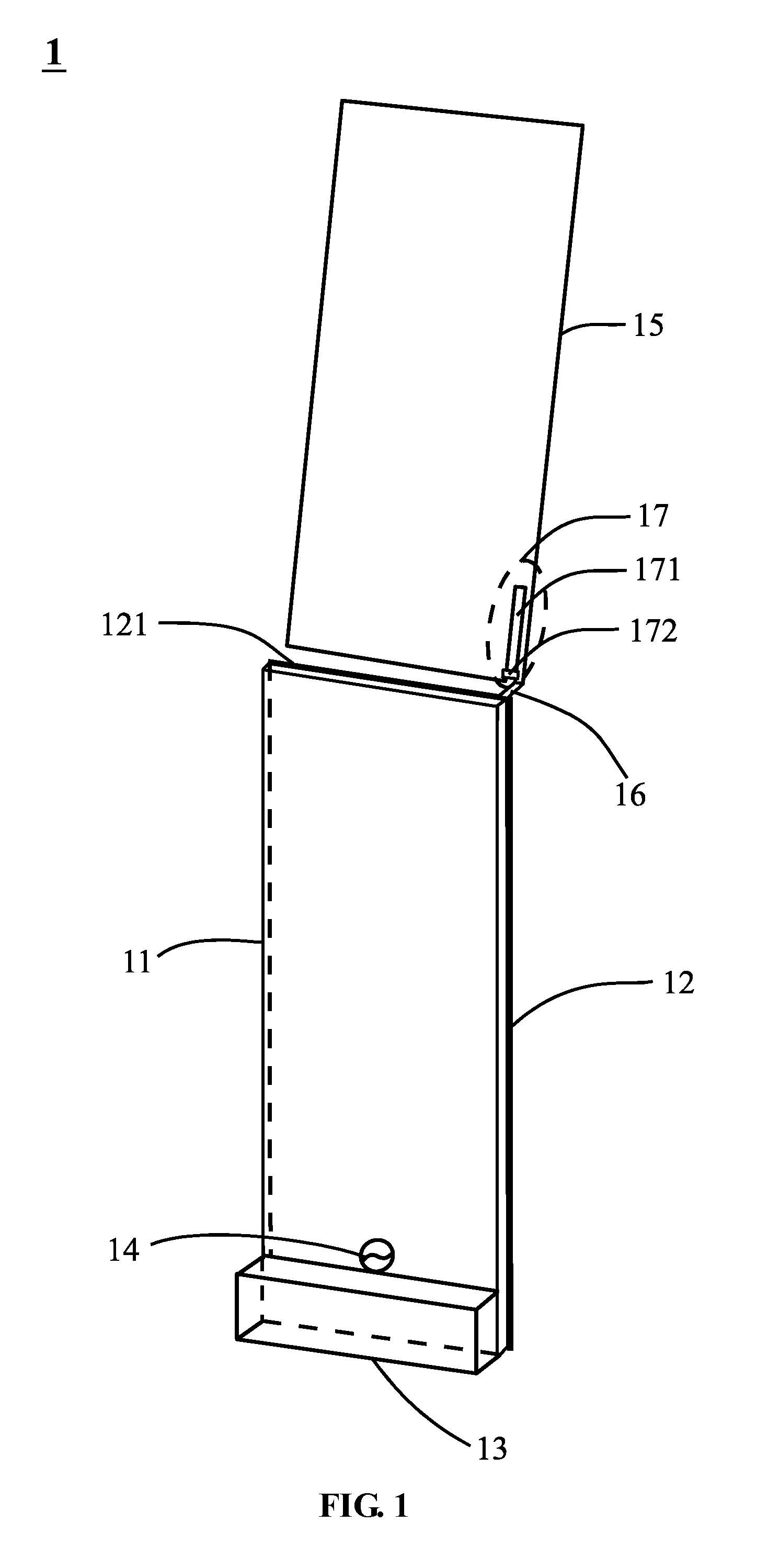
[0013]FIG. 1 shows a structural diagram for a first embodiment 1 of the mobile communication device according to the present invention. The mobile communication device comprises a dielectric substrate 11, a first ground plane 12, an antenna element 13, a second ground plane 15 and an equivalent band-stop circuit 17. The first ground plane 12 is formed on the dielectric substrate 11 by means of etching or printing technique. The antenna element 13 is disposed on or nearby the dielectric substrate 11 and is electrically connected to a signal source 14 located on the dielectric substrate 11. The second ground plane 15 is disposed in close proximity to one edge 121 of the first ground plane and electrically connected to the first ground plane 12 through a metal strip 16. The equivalent band-stop circuit 17 is disposed on the second ground plane 15 and in vicinity of the metal strip 16 and comprises a slit 171 whose open end being close to the metal strip 16 and a capacitive element 172 ...


PUM


Abstract

The present invention is related to a mobile communication device. The device comprises a dielectric substrate, a first ground plane, an antenna element, a second ground plane, and an equivalent band-stop circuit. The first ground plane is disposed on the dielectric substrate. The antenna element is disposed on the dielectric substrate or nearby the dielectric substrate and is connected to a signal source disposed on the dielectric substrate. The second ground plane is disposed nearby one edge of the first ground plane and is connected to the first ground plane through a metal strip. The equivalent band-stop circuit is disposed on the second ground plane and includes a slit and a capacitive element. The open end of the slit is near the metal strip. The capacitive element is mounted across the slit.

Description

BACKGROUND OF THE INVENTION[0001]1. Field of the Invention[0002]The present invention relates to a mobile communication device, and in particular to a mobile communication device capable of reducing the effect upon the built-in antenna thereof by the ground plane.[0003]2. Description of Related Art[0004]As the development and progress in wireless communication technologies continue to grow, various wireless communication products emerge and mobile phones become increasingly popular. Currently available mobile phones are commonly classified as bar-type, folder-type and slider-type. Among different types of mobile phone, since the system ground plane used in the mobile devices varies, the antenna applied thereto may be different as well. Taking the folder-type mobile phone as an example, compared to the bar-type mobile phone, the system ground plane thereof is formed by the upper-board ground plane and the main-board ground plane; therefore, if the antenna in the bar-type mobile phone...

Claims


Application Information

Patent Timeline
Patent Type & Authority Patents(United States)
IPC IPC(8): H01Q1/48H01Q1/24
CPCH01Q1/243H01Q1/48H01Q1/52
Inventor WONG, KIN-LULEE, CHENG-TSE
Owner ACER INC
Why Eureka
Try Eureka